Woof Meter Jed Margolin 11/8/2021
The Woof Meter is for testing subwoofer speakers to measure their Thiele-Small (TS) parameters. These parameters are necessary in order to properly design the speaker cabinet. Sometimes you might not have the TS parameters for a subwoofer speaker you want to use and sometimes the TS parameters provided by the speaker manufacturer are wrong.
To measure the TS parameters of a subwoofer you need a sensitive voltmeter with a good low frequency response. Your voltmeter might not have a low-frequency response that is good enough for testing subwoofers.
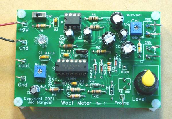
The Woof Meter contains a low frequency preamp, a precision full-wave rectifier, and a DC filter. It has a voltage output that can be read with any standard DC Voltmeter. It also has a current output for use with an analog 1mA meter.
The Woof Meter is a companion to my Precision Low Frequency Signal Generator which produces a User-selected signal from 10Hz to 90Hz with 0.1Hz resolution. The frequency is displayed on a 16x2 LCD. For the Precision Low Frequency Signal Generator Click Here.
You can use a 9V transistor battery for power. This makes the Woof Meter float so it will not be subject to ground loops. It will last a long time on the battery.
The skill level for stuffing the board is: Intermediate. Make sure you use a temperature-controlled soldering iron. I use a temperature of 340 degrees Celsius. And don’t inhale the solder fumes. If you don’t have a fume hood use a fan to blow the solder fumes away from you.
To use it:
1. Connect a Precision Low Frequency Signal Generator to the subwoofer through a 100 Ohm resistor which turns the voltage output of the signal generator into a current source. (The 100 Ohms is much greater than the 4 Ohm or 8 Ohm speaker.)
2. Connect the speaker terminals to the input to the Woof Meter.
3. Adjust the input pot R4 so that the pre-amp doesn’t clip.
4. Adjust Level pot R8 (or a Real Pot if that is what you are using) so that you get the output you need, either with the analog 1mA meter or with a voltmeter connected to the voltage output. If you use both you should adjust the level for the 1mA meter first, then adjust trimpot R14 to produce a convenient reading on your voltmeter. That way you can use the analog meter for a coarse reading and the voltmeter (assuming it is a digital meter) for a fine reading.
The testing of subwoofer speakers and the design of subwoofer cabinets is beyond the scope of this article. I recommend the following:
1. For testing subwoofer speakers to derive the Thiele-Small (TS) parameters: Measuring Loudspeaker Parameters by Rod Elliott
Basically, you:
a. Connect a Precision Low Frequency Signal Generator to the subwoofer speaker through a 100 Ohm resistor. This makes the output a current source. You will need a sensitive voltmeter with a good low frequency response or you can use this Woof Meter which contains a low frequency preamp, a precision full-wave rectifier, and a DC filter. It has a voltage output that can be read with any standard DC meter. It also has a current output for use with an analog 1mA meter. For the Precision Low Frequency Signal Generator project Click Here.
b. Find the free air resonant frequency of the speaker. That is where the voltage across the speaker is at a maximum.
c. Find the higher and lower frequencies where the response is down 3dB. That is 0.707 of the voltage (or current) at resonance.
d. Add a weight of 25 grams to the speaker cone. A U.S. nickel weighs exactly 5.0000 grams so tape 5 nickels onto the cone. (Use masking tape.)
e. Repeat the above tests: find the resonant frequency and the two -3dB frequencies.
f. There are other things for you to measure (with a standard multimeter).
g. Plug your measurements into the proper formulas and you will get the TS parameters. Then you can design the cabinet.
2. For designing subwoofer cabinets for vented, sealed, and custom bandpass cabinets: https://www.ajdesigner.com/speaker/ . Also see: http://www.mh-audio.nl/Loudspeakers.html#top
Files
I am providing the following files:
1. Schematic: jm_woof-meter_schematic.pdf
2. Bill of Material: jm_wmeter-r1-bom.pdf
3. Gerber files: jm_wmeter-r1.zip
You can order blank PC Boards from PCBWAY (they will give me a small royalty):
https://www.pcbway.com/project/shareproject/Woof_Meter.html
Notes
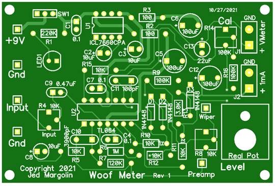
1. This is the bare board top:
This is the bare board bottom:
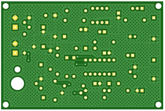
The good ground plane coverage didn’t happen by accident. It certainly didn’t happen by using the auto-router. I placed the parts and routed all of the traces by hand to get good ground plane coverage.
2. The ICL7660CPA converts +9V to -9V for the TL064 opamp.
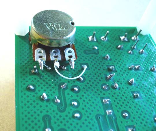
3. To use a Real Pot, do not stuff trimpot R8. Install a real pot in the hole marked “Real Pot”. You need to connect your real pot to the traces on the board. The outer terminals connect to the outer terminals of the pads for R8. Since the wiper pin (center pin) of R8 is difficult to attach a wire to when a real pot is mounted, I brought it out to a separate pad marked “Wiper”.
4. I put the ICs in sockets. Always use sockets with machine-tooled pins. The sockets with leaf-springs are crap.
5. There are two outputs. One is for a DC Voltmeter (analog or digital). The other is for a 1mA analog meter. I use one that I got on eBay where it is called: Analog Panel Meter 1mA DC 0-1mA 85C1 meter.
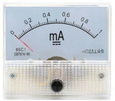
I have bought several and I always buy two at a time so that there is a good chance that at least one will work. The reason is that the meter uses a D’Arsonval movement.
From https://instrumentationtools.com/darsonval-movement/
Principle of D’Arsonval Movement
When an electric current is passed through a coil placed in a magnetic field, it experiences a force. This force causes a torque in the coil that is fixed to a spindle. The spindle can rotate in fixed bearings. The rotation of the spindle is proportional to the electric current passed through the coil. This torque that is produced is balanced after a movement against the restoring torques of springs. The torque that is produced that tends to rotate the spindle is termed a D’Arsonval Movement.
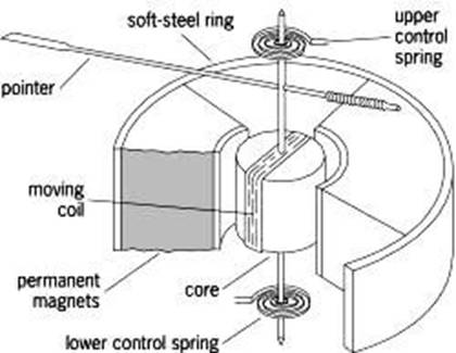
The springs are also used as conductors to connect to the coil. With a 1mA meter the force produced by the current is small so the springs that the force works against are weak. As a result if you shake the meter (gently) the moving coil (on the bearings) will move. With the jostling that the meter undergoes during shipping the bearings can be damaged. This is true no matter how well the meter itself is packed.
There is a way to help it survive shipping. Because the meter movement is a coil in a magnetic field it is not only a motor, it is also a generator. If you short the meter terminals together the “generator” will be working against a load which will make it harder for the “generator” to turn. It won’t completely keep it from turning but it will help it survive. All ammeters should be shipped with the terminals shorted. Unfortunately, none of the eBay sellers that I have bought these meters from have done this. It’s a shame, because the 85C1 is a really nice meter.
You can test this yourself. With the meter terminals not shorted, gently shake the meter in the direction so that the pointer moves. Then short the terminals and gently shake it again the same way. You will see the pointer move less.
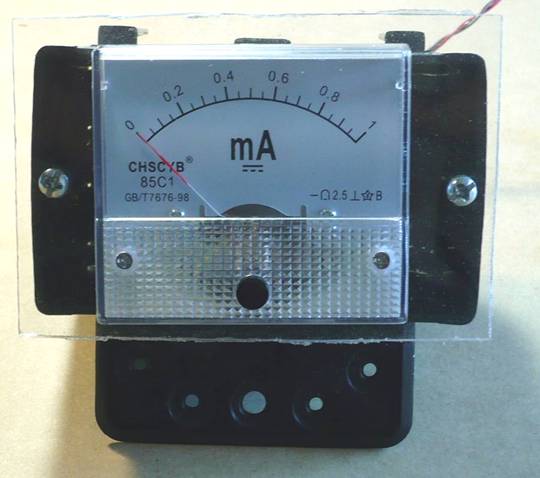
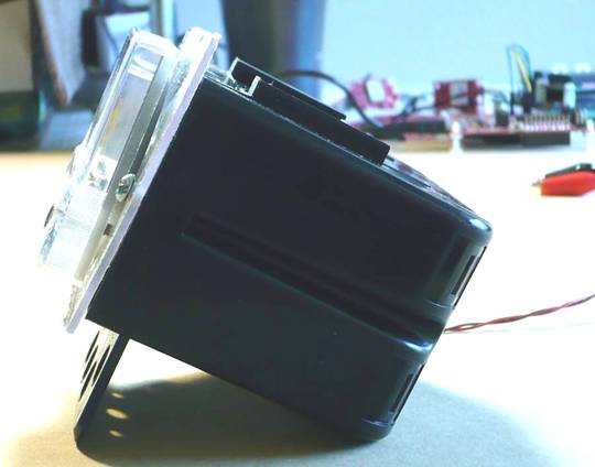
I mounted my analog meter on a piece of clear acrylic (like Plexiglas) and mounted that in an electrical box. This allows me to have the meter tilt up at an angle.
Whether you use this analog meter or a DVM, Happy Subwoofer testing and building.
Jed Margolin
Virginia City Highlands
Storey County
Nevada
11/8/2021 Updated 1/2/2022
.end