Analysis of Barrows
Jed Margolin
Mr. {Person}: Other Relevant Material
Mr. {Person} Reference: Alaskan Flight Trials of a Synthetic Vision System for Instrument Landings of a Piston Twin Aircraft, Andrew K. Barrows, Keith W. Alter, Chad W. Jennings, and J. David Powell, Department of Aeronautics and Astronautics, Stanford University, Stanford, CA; Presented Apr 1999 at the SPIE Enhanced and Synthetic Vision conference, Orlando, FL.
1. INTRODUCTION:
In the Introduction, Barrows et al. say: “Synthetic vision systems for aircraft have been investigated in a research setting for several decades.”
The Aerospace Industry is very fond of saying this even though there is no evidence for it.
1. The term synthetic vision has had different meanings over the years. Ten years ago the FAA defined synthetic vision as a display of the data from a Radar or Forward-Looking Infrared (FLIR) sensor.
2. The FAA’s current definition is: Synthetic vision means a computer-generated image of the external scene topography from the perspective of the flight deck that is derived from aircraft attitude, high-precision navigation solution, and database of terrain, obstacles and relevant cultural features. {Ref. 10b}
3. There was an article in the December 2008 issue of AUVSI Unmanned Systems magazine entitled Synthetic Vision Technology for Unmanned Systems: Looking Back and Looking Forward by Jeff Fox, Michael Abernathy, Mark Draper and Gloria Calhoun. {Ref. 10c} The article contains a number of references which the authors claim show synthetic vision going back quite a long time. However, the references that predate ‘073 do not show synthetic vision. {Ref. 10d}
4. I am beginning to suspect that many people think anything that uses 3D graphics is synthetic vision.
The department where the Authors worked is the Stanford GPS Laboratory. (http://waas.stanford.edu/)
They have a long list of publications that have been published by the members of their department going back to 1982. (http://waas.stanford.edu/pubs/index.htm)
I have not read every paper and the list is too long to reproduce here in its entirety. I have listed the titles only, except for the ones most likely to be of at least some interest, starting with 1996 and working backward.
1996
Barrows, Andrew K., Demoz Gebre-Egziabher, Roger Hayward, Renxin Xia, and J. David Powell
GPS-Based Attitude and Guidance
Displays for General Aviation [ PAPER
(in PDF) ] Presented at IEEE Emerging Technologies and Factory Automation
'96,
Barrows, Andrew K., Per Enge, Bradford W. Parkinson and J. David Powell,
Flying Curved Approaches and Missed Approaches: 3-D Display Trials Onboard a
Light Aircraft [ PAPER
(in PDF) ] Presented at the ION Conference,
Study of WAAS Ionospheric Integrity
The Effect of the Ionosphere and C/A Frequency on GPS Signal Shape: Considerations for GNSS2 [
System Identification of a Farm Vehicle Using Carrier-Phase Differential GPS
Performance Evaluation of
On-Airport Local Area Augmentation System Architectures
GPS Based Attitude Determination On Nonaligned Antenna Arrays
A Comprehensive Integrity Verification Architecture for On-Airport LAAS Category III Precision Landing
Carrier Differential GPS for
Real-Time Control of Large Flexible Structures
GPS Receiver Development and
Verification Tests for the Stanford Gravity Probe B Relativity
Carrier Phase DGPS for Closed-Loop Control of Farm and Construction Vehicles
A New Motion-Based Algorithm for GPS Attitude Integer Resolution
Automatic Steering of Farm
Vehicles Using GPS
Techniques for Real-Time Control
of Flexible Structures using GPS
Digital Tracking Filters with High Order Correlated Measurement Noise
1995
An Examination of the Relative Merits of Various Sensors for Vehicle Navigation
Barrows, Andrew, Per K. Enge, Bradford W. Parkinson, David Powell
Flight Tests of a 3-D Perspective-View Glass-Cockpit Display for General
Aviation Using GPS
[ PAPER
(in PDF) ] Presented at ION GPS '95, Palm Springs, California. September
1995
Chao, Y.C., Y.J. Tsai, Todd Walter,
Changdon Kee, Per Enge, Bradford W. Parkinson
An Algorithm for Inter-frequency
Bias Calibration and Application to WAAS Ionosphere Modeling
Precision Landing Tests with
Improved Integrity Beacon Pseudolites
Observed GPS Signal Continuity
Interruptions
Aircraft Tracking using GPS
Position and Velocity Reports
Maintaining GPS Positioning in
Steep Turns Using Two Antennas
Kinematic GPS for Closed
Global Optimization of GPS
Augmentation Architectures using Genetic Algorithms
Weighted RAIM for Precision
Approach
GPS as a Structural Deformation
Sensor
A New Method for Coverage
Prediction for the Wide Area Augmentation System (WAAS)
A Real-Time Architecture for
Kinematic GPS Applied to the Integrity Beacon Landing System
A History Of Satellite Navigation
Automatic Landing of a 737 using
GNSS Integrity Beacons
High Integrity GPS-Based
Precision Landing Using Integrity Beacon Pseudolites
The Ionospheric Delay Model Improvement for the Stanford WAAS Network
Evaluation of Orbit and Clock Models for Real Time WAAS
1994
Space Flight Tests of Attitude
Determination using GPS
Flight Test Results of Autocoupled Approaches using GPS and Integrity Beacons
Communication Protocols for
GPS-based Surveillance and TCAS
Calibration of Multipath Errors
on
Development of a GPS Receiver for Reliable Real-Time Attitude Determination in Space
Analysis of Angular Velocity Determination Using GPS
GPS Pseudolite
Signal Design
Autonomous Integrity Monitoring for GPS-based Precision Landing using Ground-based Integrity Beacon Pseudolites
Simulation-Based Evaluation of
WAAS Performance: Risk and Integrity Factors
Antenna Baseline and Line Bias Estimation Using Pseudolites for GPS-based Attitude Determination
Walter, Todd; C. Kee, Y.C. Chao, Y.J. Tsai, U. Peled, J. Ceva, A. K. Barrows, E. Abbott, David Powell, Per Enge, and Bradford Parkinson
Flight Trials of the Wide-Area
Augmentation Systm (WAAS)
[ PAPER
(in PDF) ] Presented at ION GPS 1994,
Real-Time Flight Testing Using Integrity Beacons for GPS Category III Precision Landing
Wide Area
Differential GPS as a Future Navigation System in the
A New Approach to GPS Integrity
Monitoring Using Prior Probability Models and Optimal Threshold Search
Integrity in Cycle Ambiguity Resolution for GPS-based Precision Landing
Achieving Required Navigation Performance using GNSS for Category III Precision Landing
Analysis of Spacecraft Attitude Measurements using Onboard GPS Presented at AAS Conference,
Autonomous Integrity Monitoring for Precision Approach using DGPS and a Ground-based Pseudolite
Theory and Design of Pseudolites
Autonomous Integrity Monitoring and Wide Area DGPS
1993
Static Test Results of Wide Area Differential GPS
The Statistics of Selective Availability and Its Effect on Differential GPS
Multipath Interference in Orbiting Receivers Due to Earth Surface Reflections
Autonomous Integrity Monitoring for Precision Approach using DGPS and a Ground-based Pseudolite
Real-time Flight Test Evaluation of the GPS Marker Beacon Concept for Category III Kinematic GPS Precision Landing
Space Flight Tests of Attitude Determination Using GPS: Preliminary Results
Application of GPS Attitude Determination
to Gravity Gradient Stablized Spacecraft
Real-time Cycle Ambiguity Resolution using a Pseudolite for Precision Landing of Aircraft with GPS
High Accuracy GPS Positioning in the Continent: Wide Area Differential GPS
Translation, Rotation and Vibration Control of Large Space Structures using Self-differential GPS (SDGPS)
Flight Tests of Attitude Determination Using GPS Compared Against an Inertial Navigation Unit
1992
Estimation of Abslute Ionospheric Delay Exclusively through Single-Frequency GPS Measurements
Generalizing Wahba's Problem for High Output Rates and Evaluation of Static Accuracy using a Theodolite
Algorithms and Implementation of Wide Area Differential GPS
Aircraft Applications of
GPS-based Attitude Determination
Proceedings of the 5th International Technical Meeting of the Satellite
Division of the Institute of Navigation ION GPS 1992, September 16 - 18, 1992;
Albuquerque, NM; pages 775 - 782
http://www.ion.org/search/view_abstract.cfm?jp=p&idno=4654
Abstract: Extensive flight testing has been conducted on a single- engine Piper Dakota to explore new applications of attitude determination using GPS for aircraft. Combined with the navigation function of GPS, real time heading and attitude sensing at 10 Hz to better than 0.1 deg RMS using GPS offers an attractive supplement to existing cockpit instrumentation. An exciting new application of attitude sensing using GPS is the estimation of the aircraft dynamic model in flight. Dynamic response data obtained through GPS can be used to estimate aircraft stability derivatives, design optimal autopilots, and augment RAIM. Real time estimation of wing flex using GPS to measure instantaneous wing loading is an added benefit. Cycle ambiguities are resolved through the natural aircraft attitude motion, consisting of banks, turns, or small attitude motion. Attitude motion modulates the measurements of GPS carrier phase with a signature that is used to identify the cycle ambiguities within seconds. Unlike search techniques, the motion-based approach is not vulnerable to false solutions, even for arbitrarily long baselines. The paper presents and analyzes flight data showing the short-period, phugoid, and Dutch roll modes resulting from impulsive inputs to the controls.
Integer Ambiguity Resolution of the GPS Carrier for Spacecraft Attitude Determination
1991
Expanding the Performance Envelope of GPS-Based Attitude Determination
Mitigating Multipath Error in GPS-based Attitude Determination
1990
Wide Area Differential GPS
Techniques for Autonomous GPS Integrity Monitoring
1989
1988
Receiver Autonomous Integrity Monitoring of the Navigation Service Provided by the Global Positioning System
Aircraft Automatic Landing Systems Using GPS
Autonomous GPS Integrity Monitoring Using the Pseudorange Residual
Aircraft Automatic Landing
Systems Using GPS
A Basis for the Development of Operational Algorithms for Simplified GPS Integrity Checking
1987 and prior years
A Basis for the Development of Operational Algorithms for Simplified GPS Integrity Checking
Simplified GPS Integrity Checking with Multiple Satellites
Optimal Locations of Pseudolites for Differential GPS
The Use of Pseudo-Satellites for Improving GPS Performance
NAVSTAR: Global Positioning System - Ten Years Later
The Application of NAVSTAR Differential GPS in the Civilian Community
The reports that hold the most promise are (and we will add Mr. {Person’s} reference and number them):
Barrows 5
Barrows, A. Alter, K, Jennings, C.,
and Powell, J.D.
Alaskan Flight Trials of a Synthetic Vision System for Instrument Landings
of a Piston Twin Aircraft [ PAPER (in
PDF) ] Presented Apr 1999 at the SPIE Enhanced and Synthetic Vision
conference, Orlando, FL
Barrows 4
Barrows, Andrew K., Demoz Gebre-Egziabher, Roger Hayward, Renxin Xia, and J. David Powell
GPS-Based Attitude and Guidance
Displays for General Aviation [ PAPER
(in PDF) ] Presented at IEEE Emerging Technologies and Factory Automation
'96,
Barrows 3
Barrows, Andrew K., Per Enge, Bradford W. Parkinson and J. David Powell,
Flying Curved Approaches and Missed Approaches: 3-D Display Trials Onboard a
Light Aircraft [ PAPER
(in PDF) ] Presented at the ION Conference,
Barrows 2
Barrows, Andrew, Per K. Enge, Bradford W. Parkinson, David Powell
Flight Tests of a 3-D Perspective-View Glass-Cockpit Display for General
Aviation Using GPS
[ PAPER
(in PDF) ] Presented at ION GPS '95, Palm Springs, California. September
1995
Barrows 1
Walter, Todd; C. Kee, Y.C. Chao, Y.J. Tsai, U. Peled, J. Ceva, A. K. Barrows, E. Abbott, David Powell, Per Enge, and Bradford Parkinson
Flight Trials of the Wide-Area
Augmentation System (WAAS)
[ PAPER
(in PDF) ] Presented at ION GPS 1994,
[The full links to the Barrows reports are in Ref. 10e]
In Barrows 5 (1. INTRODUCTION):
In 1994,
work was begun at
This sounds like it could be a problem for ‘073. It isn’t. The problem is that Mr. {Person} has started at the end of the story with the April 1999 report Alaskan Flight Trials of a Synthetic Vision System for Instrument Landings of a Piston Twin Aircraft (Barrows 5).
We will start at the beginning.
Barrows 1 [Flight Trials of the Wide-Area Augmentation Systm (WAAS), September 1994]
Stanford conducted Flight Trials of the Wide-Area Augmentation System (WAAS) over several days in mid-August 1994. It was not synthetic vision. There was no suggestion of synthetic vision or even a 3D display of anything.
From the ABSTRACT:
The Wide-Area Augmentation System (WAAS) is being rapidly developed by the Federal Aviation Administration for supplemental operational use in 1997. In time, it will be a primary navigation aid for all phases of flight down to Category I precision approach. The WAAS will include a network of approximately 20 to 30 Wide-area Reference Stations (WRSs) distributed around the National Airspace System. These reference stations will observe all GPS satellites in view and send pseudorange and ionospheric observations back to one or more Widearea Master Stations (WMSs). The WMSs will use this data to form vector corrections for each GPS satellite. These vectors contain separate components for the satellite ephemeris, satellite clock and ionosphere. The corrections will be broadcast to WAAS users via a geostationary satellite, using a signal and data format, which has been designed by RTCA Special Committee 159.
From Section 5 AVIONICS
The approach guidance was generated by a laptop computer connected to a 5 inch flat panel monitor on the instrument panel. As shown in Figure 7, indications to the pilot were the same as those from a standard ILS: moving needles for horizontal and vertical approach path deviations, marker beacon lights to indicate designated points along the approach, and numerical readouts of height above runway (in feet) and distance to touchdown (in nautical miles). Localizer needle deflections were based on angular deviation from the localizer beam (6° beamwidth), with the synthetic localizer antenna placed 4800 feet from the touchdown point. The synthetic glideslope antenna was placed 180 feet from the approach end of the runway and generated a 4° glideslope with a 1.4° beamwidth (4° was used instead of the standard 3 because there is a hill off the approach end of the runway).
Glideslope needle deflection was based on angular deviation from glidepath until the aircraft was 100 feet above the runway. At this point, the glideslope display was switched from an angular to a linear deviation indicator to eliminate the familiar problem of the ILS glideslope needle becoming overly sensitive just before touchdown. Virtual middle and inner marker beacons were placed under the approach path to indicate that the pilot was passing through altitudes of 200 and 50 feet above the runway. The pilot’s display lit up an amber “M” or white “I” when the aircraft flew over these beacons. All antenna locations and needle sensitivities were chosen to accurately reproduce a standard ILS approach.
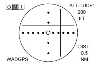
Figure 7 The WADGPS precision approach guidance display. Here the aircraft is shown to be below and to the left of desired glidepath. The middle marker beacon light is on, indicating aircraft is at 200 feet altitude
From FLIGHT TRIALS
The flight trials were conducted over several days starting from mid-August 1994. Unfortunately, due to severe problems with our temporary UHF data link, the differential solutions were not always received by the airborne receiver. Consequently, many of the approaches that were flown did not have real-time differential corrections. Fortunately, we did have seventeen approaches, from two different days, in which differential corrections were applied throughout a significant part of each approach. However, because of the data link dropouts, several of these approaches have corrections whose age is in excess of 60 seconds. Despite these less than ideal conditions the results have been outstanding. Figures 12 and 13 summarize these results.
Summary of Barrows 1: Stanford conducted Flight Trials of the Wide-Area Augmentation System (WAAS) over several days in mid-August 1994. It was not synthetic vision. There was no suggestion of synthetic vision or even a 3D display of anything.
Barrows 2 [Flight Tests of a 3-D Perspective-View Glass-Cockpit Display for General Aviation Using GPS, September 1995]. This is the first report of the Tunnel-in-the-Sky project.
A display that takes advantage of the three-dimensional positioning data available from differential GPS has been flight tested on a general aviation aircraft. This glass-cockpit instrument provides a natural, “out the window” view of the world, making the horizon, runway, and desired flight path visible to the pilot in instrument flight conditions. The flight path is depicted as a series of symbols through which the pilot flies the airplane. Altitude, heading, and airspeed are presented along with lateral and vertical glidepath deviations. Particular attention was given to demonstrating a system satisfying the budget, power, and form-factor constraints of light aircraft.
Simulator tests and flight trials on a Piper Dakota aircraft showed that the tunnel display allows the pilot to hand fly straight-in approaches with equivalent or better flight technical error than with a typical Instrument Landing System (ILS) needle display. Additionally, the tunnel display provides lateral and vertical guidance on curving missed approach procedures, for which ILS cannot provide positive course guidance. The results demonstrate that GPS-based displays can improve navigation along straight and curving flight paths in light aircraft by enhancing pilot situational awareness. Better pathfollowing accuracy will benefit future Air Traffic Control schemes and a variety of specialized applications.
{Emphasis added}
What does Barrows mean by an “out the window” view of the world? It sounds like synthetic vision, but it isn’t.
INTRODUCTION
To address this need, a display was developed that allows the pilot of a light aircraft to see a three-dimensional (3-D) picture of the outside world, including the desired flight path and runway environment, even in low visibility conditions. This display has been tested in piloted simulations and flight trials, and offers significant benefits over conventional displays.
In this report the 3D picture of the world is only the horizon, runway, and desired flight path visible to the pilot in instrument flight conditions.
From Tunnel Display:
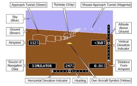
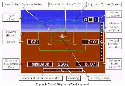
The tunnel display, shown in Figure 2, was kept simple to minimize computational requirements and enhance ease of use. The background consisted of the ground in brown, the sky in blue, and a white horizon line to provide the information found on a standard artificial horizon. The field of view represented was 40 deg vertical by 50 deg horizontal and included the runway and control tower depicted in correct perspective. (Other features could have been added, such as taxiways, roads, and water, but at some computational expense.) The approach path was depicted as a series of green “hoops” and the missed approach path as a series of magenta hoops whose pentagonal shape gave an up/down cue to the pilot.
Here is Figure 2: Tunnel Display:
The section Tunnel Display ends with:
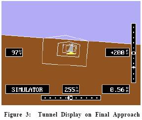
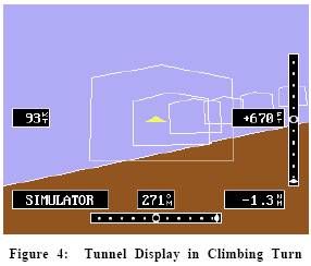
The 3-D scene could be replaced by a full-screen ILS needle display for comparative testing. Views of the 3-D display on final approach and in a climbing right turn are shown in Figures 3 and 4, respectively.
Here are Figures 3 and 4:
If you look closely in Figure 2 and Figure 3 you will see the runway represented as a 3D projected rectangle.
That is what Barrows means (and shows) as a “three-dimensional (3-D) picture of the outside world.” There is no digital terrain elevation database. It is not synthetic vision.
Barrows
2 does not say when the work was performed but it had to be between mid-August
1994 (Barrows 1 WAAS) and when the report was presented (ION GPS '95,
Summary of Barrows 2: The phrase “three-dimensional (3-D) picture of the outside world” means a runway represented as a 3D projected rectangle. It is not synthetic vision.
Barrows 3 [Flying Curved Approaches and Missed Approaches: 3-D Display Trials Onboard a Light Aircraft] September 1996. This is an update to Barrows 2.
In INTRODUCTION:
A display that fully utilizes this 3-D information was developed that allowed the pilot to see a perspective picture of the outside world, including the desired flight path and runway environment, even in low visibility conditions.
{Emphasis added}
Compare this to Barrows 2:
A display that takes advantage of the three-dimensional positioning data available from differential GPS has been flight tested on a general aviation aircraft. This glass-cockpit instrument provides a natural, “out the window” view of the world, making the horizon, runway, and desired flight path visible to the pilot in instrument flight conditions. The flight path is depicted as a series of symbols through which the pilot flies the airplane. Altitude, heading, and airspeed are presented along with lateral and vertical glidepath deviations. Particular attention was given to demonstrating a system satisfying the budget, power, and form-factor constraints of light aircraft.
Figure 1 in Barrows 3 is a slightly different version of Figure 2 in Barrows 2:
If you look closely, the very center of the picture shows the runway represented as a 3D projected rectangle.
This report does not say when
the work was performed but it had to be after Barrows 2 (September 1995) and
when the report was presented at the ION Conference,
(This updated report of Tunnel-in-the Sky appears to have come with MATLAB video.)
Summary of Barrows 3: An update of Barrows 2. It still does not show synthetic vision.
Barrows 4 – GPS-Based Attitude and Guidance Displays for General Aviation, November 1996
GPS was used with a short baseline (1 and 2 wavelengths) triple antenna configuration to obtain attitude in conjunction with solid state rate gyros. The system was used to provide an inexpensive Attitude-Heading Reference System (AHRS) for use by small General Aviation aircraft.
Then it was used with the Tunnel Display.
Abstract - GPS was used with a short baseline (1 and 2 wavelengths) triple antenna configuration t o obtain attitude in conjunction with solid state rate gyros. The system was used to provide an inexpensive Attitude-Heading Reference System (AHRS) for use by small General Aviation aircraft. The gyros enabled a high bandwidth output while the GPS was used to estimate the gyro drift rate. The resulting attitude information was used, along with GPS-based position, by a graphical “out-the-window” view with tunnels indicating the desired path in the sky for the current phase of flight. Accuracy and ease of flying are enhanced by the system.
This is the Tunnel Display again:
III. DISPLAY SYSTEM DESCRIPTION
A. Introduction
The attitude algorithms previously described make it possible to take full advantage of differential
GPS by presenting the pilot of a light aircraft with a three-dimensional (3-D) picture of the "out-the-window" view. Such a display intuitively depicts the desired flight path and runway environment even in instrument flight conditions. A prototype display was developed and tested in piloted simulations and in flight, demonstrating some significant benefits over conventional displays.
And, later in the paragraph:
To enhance situational awareness, researchers have been working for some time on displays that
integrate the many data sources needed for flight with a 3-D perspective view of the outside world.
The desired flight path is presented as a tunnel or series of symbols for the aircraft to fly through and has been called a “highway-in-the-sky”, “pathway-in-the-sky”, or “tunnel” [7-9].
In B. System Description:
Differential GPS (DGPS) was used to provide positioning data to the display. It was a mini
version of the FAA's Wide Area Augmentation System (WAAS) [11,12] that is scheduled to
become available to all aircraft in 1998. It provides 2 m 95% vertical accuracy, enabling scenes
reconstructed from a 3-D database to very closely match the actual view out the cockpit window. GPS attitude augmented with rate gyros was also a critical component of the 3-D perspective display system, since a data latency less than 100 msec was needed to create a smooth picture with no perceptible lag. The 3-D scene was presented on a 320x234 pixel 5.5 inch diagonal active-matrix liquid crystal display (AMLCD) attached to the instrument panel glareshield.
{Emphasis added}
Barrows 4 uses the same mantras as Barrows 2, and 3:
a 3-D perspective view of the outside world.
enabling scenes reconstructed from a 3-D database to very closely match the actual view out the cockpit window.
(What is new in Barrows 4 is researchers have been working for some time)
And here is the Tunnel again. This time it’s Figure 5.
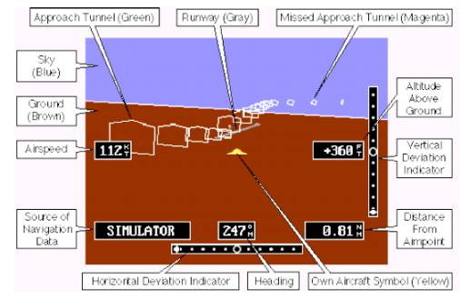
We have seen this 3D perspective display system before. Airspeed: 112 KT; Heading: 247 degrees; Altitude: 360 ft; Distance from Airport: 0.81 NM. This is the same picture shown in Barrows 2 as Figure 2, except the color of the “ground” is different.
This report does not say when the work was performed, but it was probably between Barrows 3 (September 1996) and when the paper was presented at IEEE Emerging Technologies and Factory Automation '96, Kauai, HI, November 1996.
Barrows
5 - Alaskan Flight Trials of a Synthetic Vision
System for Instrument Landings of a Piston Twin Aircraft Presented Apr 1999
at the SPIE Enhanced and Synthetic Vision conference, Orlando , FL
This is the report cited by Mr. {Person}. Now that we have covered Barrows’ previous reports we can properly understand this one.
In the INTRODUCTION Barrows has said:
Synthetic vision systems for aircraft have been investigated in a research setting for several decades.
Now we know that this statement is patently false.
We know from Barrows 1 (1994) that Stanford conducted Flight Trials of the Wide-Area Augmentation System (WAAS) over several days in mid-August 1994. It was not synthetic vision. There was no suggestion of synthetic vision or even a 3D display of anything.
We know from Barrows 2 (September 1995) that when he used the phrase “three-dimensional (3-D) picture of the outside world” he meant a runway represented as a 3D projected rectangle. It is not synthetic vision.
Barrows 3 (September 1996) was an update of Barrows 2 that still did not show synthetic vision.
Barrows 4 (November 1996) did not add anything to Barrows 3. His 3-D perspective view of the outside world and enabling scenes reconstructed from a 3-D database to very closely match the actual view out the cockpit window meant representing the runway as a 3D rectangle. There was no terrain.
It was in Barrows 4 that he first made the statement researchers have been working for some time (on synthetic vision.)
In Barrows 5 this has become Synthetic vision systems for aircraft have been investigated in a research setting for several decades. The evidence says this is not true.
Barrows 5 is the first Barrows report to discuss the Digital Terrain Elevation Database. In Section 2. BACKGROUND:
Digital terrain source data continues to
become more readily available over time. Much of the currently available
information is derived from declassified military digital terrain elevation
data (DTED). Accurate terrain data for the
This is also the first Barrows report to show synthetic vision.
In Section 4. SYSTEMS DESIGN:
In 1998, terrain information was added to the display necessitating another upgrade. A Pentium II processor running at 333 MHz was added along with an Obsidian2-based graphics board capable of drawing high speed textured polygons. While most of the display code was initially written in C at the lowest possible level, the complexity of handling terrain information prompted the addition of the OpenGVS hierarchical scene graph API from Quantum 3D, Inc.
The first figure in the Barrows reports to show synthetic vision is Figure 2 Display Tunnel with Terrain.
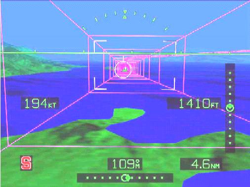
Figure 2 Display Tunnel with Terrain
Since this was added between Barrows 4 (November 1996) and the statement in Barrows 5 that terrain was added in 1998, that is the window for Barrows’ use of synthetic vision.
[The {Company’s} Report, written by Mr. {Person} recommended hiring Dr. Barrow as an Expert Witness to invalidate ‘073 and ‘724]
I think hiring Dr. Barrows as an Expert Witness is a splendid idea, so he can be asked about the various untrue and/or misleading statements in his reports.
Priority date for 5,566,073
However, I did not wake up on the morning of July 11, 1994 and decide to invent something, do a detailed patent search, write a patent application, and file the application by the end of the day. I have never been that good.
The priority date for ‘073 is June 29, 1993. {See Ref. 10f}. [This article originally said 2003, which is an obvious error – jm]
References
Reference 10a – Synthetic Vision Technology Demonstration, Volume 1 of 4, Executive Summary (FAA), Synthetic Vision Program Office Federal Aviation Administration; Malcolm A. Burgess, FAA; Terence Chang, TRW; Dale E. Dunford, USAF; Roger H. Hoh, Hoh Aeronautics; Walter F. Home, GTRI; Richard F. Tucker, TRW; December 1993; PDF page 10 and PDF pages 11,12 http://www.dtic.mil/srch/doc?collection=t2&id=ADA280564
For a local copy click here.
Reference 10b - FAA Title 14 Part 1 (Contains FAA current definition of Synthetic Vision)
Reference 10c - Synthetic Vision Technology for Unmanned Systems: Looking Back and Looking Forward by Jeff Fox, Michael Abernathy, Mark Draper and Gloria Calhoun which appeared in the December 2008 issue of AUVSI’s Unmanned Systems (page 27).
PDF – http://www.jmargolin.com/svr/refs/ref01_auvsi.pdf
Reference 10d – Synthetic Vision Technology for Unmanned Aerial Systems: The Real Story, Jed Margolin, January 7, 2009 (Response to AUVSI article)
Full Response – http://www.jmargolin.com/svr/auvsi_response_index.htm
Abridged Response – http://www.jmargolin.com/svr/auvsi_answer_summary.pdf
Reference 10e – Full links to Barrows reports
Barrows 5
Barrows, A. Alter, K, Jennings, C.,
and Powell, J.D.
Alaskan Flight Trials of a Synthetic Vision System for Instrument Landings
of a Piston Twin Aircraft [ PAPER (in
PDF) ] Presented Apr 1999 at the SPIE Enhanced and Synthetic Vision
conference, Orlando, FL
http://waas.stanford.edu/%7Ewwu/papers/gps/PDF/andyspie99.pdf
Barrows 4
Barrows, Andrew K., Demoz Gebre-Egziabher, Roger Hayward, Renxin Xia, and J. David Powell
GPS-Based Attitude and Guidance
Displays for General Aviation [ PAPER
(in PDF) ] Presented at IEEE Emerging Technologies and Factory Automation
'96,
http://waas.stanford.edu/%7Ewwu/papers/gps/PDF/att_and_displ_4ga_akb96.pdf
Barrows 3
Barrows, Andrew K., Per Enge, Bradford W. Parkinson and J. David Powell,
Flying Curved Approaches and Missed Approaches: 3-D Display Trials Onboard a
Light Aircraft [ PAPER
(in PDF) ] Presented at the ION Conference,
http://waas.stanford.edu/%7Ewwu/papers/gps/PDF/curved_approaches_akb96.pdf
Barrows 2
Barrows, Andrew, Per K. Enge, Bradford W. Parkinson, David Powell
Flight Tests of a 3-D Perspective-View Glass-Cockpit Display for General
Aviation Using GPS
[ PAPER
(in PDF) ] Presented at ION GPS '95, Palm Springs, California. September
1995
http://waas.stanford.edu/%7Ewwu/papers/gps/PDF/tunnel_display_akb95.pdf
Barrows 1
Walter, Todd; C. Kee, Y.C. Chao, Y.J. Tsai, U. Peled, J. Ceva, A. K. Barrows, E. Abbott, David Powell, Per Enge, and Bradford Parkinson
Flight Trials of the Wide-Area
Augmentation System (WAAS)
[ PAPER
(in PDF) ] Presented at ION GPS 1994,
http://waas.stanford.edu/%7Ewwu/papers/gps/PDF/waas_trials_tfw94.pdf
Reference 10f - Early Documents for 5,566,073
http://www.jmargolin.com/patents2/pilotrefs/pilotdocs.pdf
.end