Spoofing the Tektronix Readout Pin
Jed Margolin September 16, 2015 Updated 9/28/2024
(This applies to other Tektronix oscilloscopes as well.)
I have a Tektronix TAS-465 oscilloscope that I bought for a good price on eBay.
The TAS-465 is a nice digitally controlled analog ‘scope with onscreen readout.
It came with Chinese ‘scope probes which are fine except they do not have the readout pin.
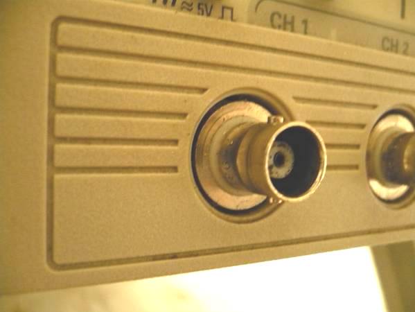
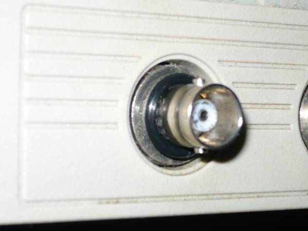
For a long time Tektronix ‘scopes have come with an isolated ring around the BNC inputs that, when connected to ground through the appropriate value resistor, tells the ‘scope if you are using a ‘scope probe with an attenuator.
The outer ring is the insulated readout ring. Then there is the white insulator. Then there is the body of the BNC connector, which is grounded.
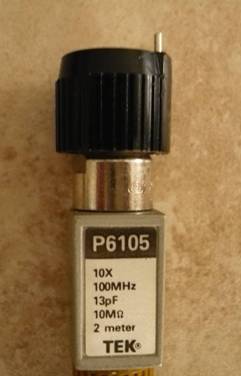
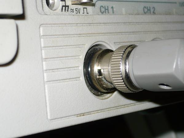
Tektronix probes connect to the readout ring with a spring-mounted pin on the ‘scope probe. Not all Tektronix ‘scope probes have this pin but I have never seen a non-Tek probe that does have it. (Note that later ‘scopes may have a menu entry to change the attenuation factor. Mine don’t.)
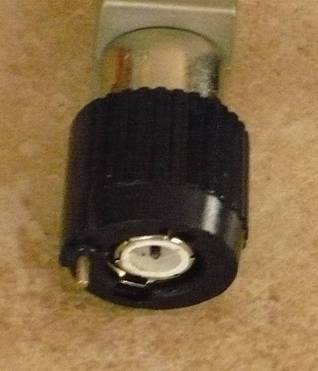
Here is the pin.
And this is what it looks like from the end of the BNC.
The most popular ‘scope probe attenuation factors are 10X and 100X. The resistor value for 10X is 11K (10K works), for 100X it is 6K (5.6K works). If someone says that all you have to do is ground the readout ring, they are wrong.
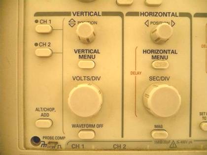
At first, the information from the readout pin simply changed the light in the on-panel gain control to illuminate the correct Volts/Division.
This is an example of the venerable 465B.
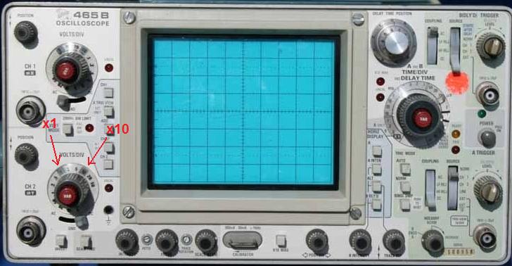
Later ‘scopes come with onscreen readouts.
With the TAS-465 there are no numbers on the on-panel gain control. The only way to see your Volts/Div is the onscreen display.
I will mention that Tektronix ‘scope probes are hideously expensive which is why used Tektronix ‘scopes rarely come with them. The Chinese ‘scope probes work fine, at least the low bandwidth ones (≤ 100 MHz).
You would think that by now someone would have come out with an adapter to spoof the readout pin. If they have I haven’t seen it.
So, this is how to cheaply spoof the Tek readout pin.
1. Get a rubber O-Ring that is 1/2" O.D x 3/8” I.D. x 1/16”. Home Depot sells one by Hillman:
As of this writing a pack of 12 costs $5.04 (updated 9/28/2024).
2. Get a length of 26 AWG tinned copper bare wire. Technically, this is called bus wire. Bus wire used to be easy and cheap to get but things have changed. You will have to find this for yourself. (Try eBay.) 26 AWG bus wire has a diameter of 0.40386 mm, which is 0.01590 inches, which is slightly more than 1/64 inch (0.015625 inch).
3. A 10K resistor. Technically, it should be 11K but 10K works fine for me. (For a 100x probe, 5.6K works.)
The Procedure
1. Put the O-Ring around the BNC jack and push it all the way back.
2. Put the ‘scope probe on. This applies force against the O-Ring so that when you wrap the 26 AWG bus wire between the O-Ring and the readout ring it will contact the readout ring.
3. Wrap the 26 AWG bus wire around the BNC jack between the O-Ring and the readout ring. Wrap it around once and twist it closed. Then connect the 10K resistor to it.
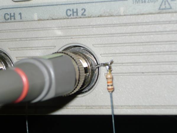
Be careful not to short your new readout wire against the body of the BNC. And if the ‘scope front panel is metal you should put a piece of electrical tape between it and the readout wire.
Also, if your front panel is plastic be careful not to melt it with your soldering iron.
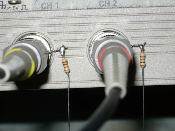
4. I am going to do both inputs.
5. Now we have to find a place to get Ground for the resistors.
a. If your cabinet has a screw on the bottom of the case, use it.
Sadly, the TAS-465 does not have a screw on the bottom of the case.
b. You could drill a small hole on the case and use a sheet metal screw but:
You have to remove the case so you don’t damage any of the components in the ‘scope when you drill the hole.
You have to make sure that when you put the case back on, the screw does damage any of the components as the case is slid back on.
c. You can wrap a wire around the body of the BNC jack for the External Trigger Input. (But you might want to spoof its readout pin, too.)
d. On the TA-465 there is a hole for a banana plug next to the Calibration signal. It’s Ground. That’s what I used.
I got a banana plug and removed the shell. The wire is 22 AWG solid wire. Use whatever wire you like.
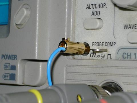
This is what it looks like:
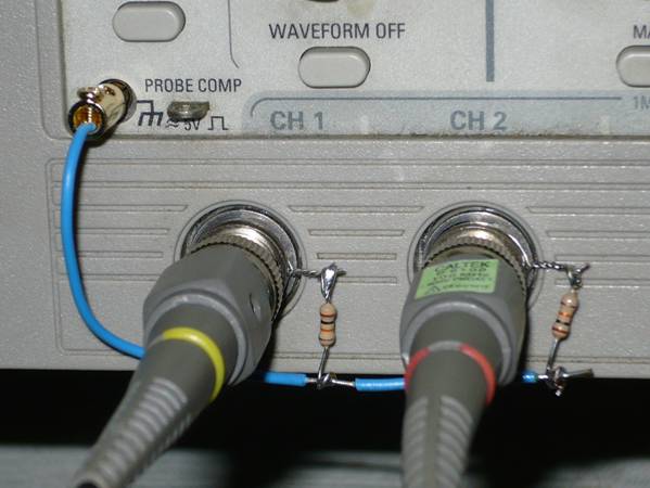
It’s not pretty but it works.
If you want, you can get a small box and put each readout pin wire on a switch and select different resistors, like None, 10K, and 5.6K. (Use one switch or switch pole per readout wire.)
Here is the Calibration Signal before spoofing the Readout Pin. The Calibration Signal is about 5Vp-p, so the ‘scope indicates 0.5 Vp-p.
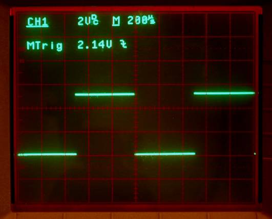
Here it is with the Readout Spoofer. (Channel 1 is 2V/Div).
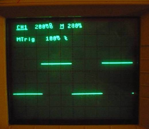
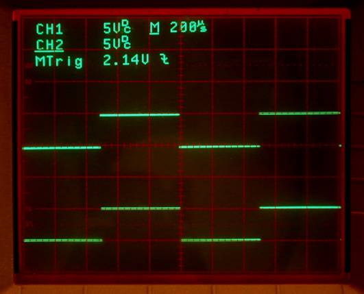
And here are both channels (5V/Div) connected to the Calibration Pin:
Once I install a Readout Spoofer I try to leave the ‘scope probe on because I don’t want the bus wire to come off. YMMV.
You might wonder, why use a ‘scope probe with 10x attenuation?
Here is a very good explanation by Ian Poole: http://www.radio-electronics.com/info/t_and_m/oscilloscope/oscilloscope-probes.php
The short version is that it increases the impedance of the probe so that it presents less of a load on the circuit you are measuring. Increasing the impedance means that the resistance is increased and the capacitance is decreased. (A higher capacitive reactance means a smaller capacitance.)
Zc = 1/(2 * π * f * C)
Also note that the higher the frequency the smaller the capacitive reactance. That is why capacitors conduct more current as the frequency increases.
Happy Spoofing.
Jed Margolin
Virginia City Highlands, Nevada
September 16, 2015
(Updated 9/28/2024)