This
article has been reproduced with the permission of the
Association for Unmanned Vehicle Systems International (AUVSI), which is the
world's largest non-profit organization devoted exclusively to advancing the
unmanned systems community. AUVSI, with members from government organizations,
industry and academia, is committed to fostering, developing, and promoting
unmanned systems and related technologies. http://www.auvsi.org/
[The article was
converted to text using OCR. Paragraph numbering was added.]
Synthetic Vision
Technology for Unmanned Aerial Systems:
Looking Back and
Looking Forward
By Jeff Fox, Michael
Abernathy, Mark Draper and Gloria Calhoun
[1] Using computers and
terrain databases to generate a simulated, real-time, three-dimensional view of
an environment-otherwise known as synthetic vision-has been applied to unmanned
aircraft systems for three decades.
[2] More recently it has
evolved away from being a piloting aid to a potentially powerful tool for
sensor operators. Technology observers expect it can help offset many factors
that currently compromise the usefulness of UAS video imagery: narrow camera
field of view, degraded datalinks, poor environmental conditions, limited
bandwidth and highly cluttered visual scenes such as those found in urban
areas.
[3] With synthetic vision
technology, information can be pulled from databases (of terrain elevation,
cultural features, maps, photo imagery) and combined with data from networked
sources, all of which can be represented as computer-generated imagery and
symbology and overlaid on a dynamic video image display. The imagery and
symbology appears to coexist with real objects in the scene, allowing an
operator to cut through the clutter and maintain situational awareness of the
environment.
[4] There is a large body
of research from the 1970s to the present that addresses the application of
synthetic vision to manned and unmanned aircraft. In the interest of brevity,
this article will focus on select systems that were important enablers toward
UAS synthetic vision systems.
[5] The story begins in the
1970s when the use of computers to create 3D real-time, out-the-window
synthetic environments was beginning to see wide acceptance for training pilots
of manned aircraft. Computer graphics company Evans and Sutherland (E&S),
of Salt Lake City, Utah, had seen the commercial potential for flight
simulation and had introduced special-purpose graphics computers, like their
Picture System, which transformed and projected 3D terrain data as simple 3D
polygons to a pilot's perspective view in real-time. In 1975, an engineering
student named Bruce Artwick wrote "Flight Simulator" for the Apple II
computer. He formed a company and in 1980 marketed the product that ultimately
became Microsoft Flight Simulator.
[6] This emergence of
computer flight simulation in the 1970s appears to have sparked a monumental
amount of research. The U.S. Air Force began its Visually Coupled Airborne
Systems Simulator (VCASS) program, with a particular eye toward
future-generation fighter aircraft ("VCASS: An Approach to Visual
Simulation," Kocian, D., 1977). NASA was developing synthetic vision for
the Super Sonic Transport and for its High Maneuverability Aircraft Testbed
(HiMAT) remotely piloted vehicle (RPV) program. Educational institutions
studied the limitless new possibilities for virtual reality human-machine
interfaces. By the mid-1980s, synthetic vision for RPV simulation was even
commercially available for radio control aircraft hobbyists.
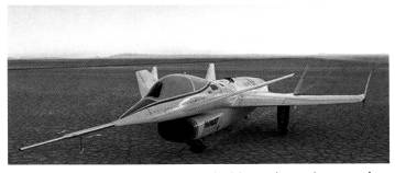
NASA's HiMAT
remotely piloted vehicle after flight at Dryden Flight Research Center. Photo
courtesy of NASA.
[7] In 1977, NASA
researcher Charles Knox published "Pathway-in-the-Sky Contact Analog
Piloting Display," which included a complete design for a synthetic vision
system. It featured a computer that projected a 3D view of the terrain given an
aircraft's position and orientation. This out-the-window perspective view was
displayed on a CRT type display. Such displays were called "Pictorial
Format" avionics systems, but we recognize them as containing all of the
essential elements of a modern synthetic vision display.
[8] In 1979, the U.S. Air
Force completed its "Airborne Electronic Terrain Map Applications
Study" and in 1981 published "The Electronic Terrain Map: A New
Avionics Integrator" describing how a computerized terrain database could
be displayed as an out-the-window 3D view allowing the pilot to "see"
even at night and in other limited visibility situations.
[9] Also in 1979, the Air
Force published research identifying human factors problems that would have to
be overcome in RPV cockpit design ("Visual- Proprioceptive Cue Conflicts
in the Control of Remotely Piloted Vehicles" by Reed in 1977). NASA would
use this in the design of the HiMAT RPV 3D visual system in 1984.
[10] Pictorial format
avionics (i.e., synthetic vision) formed a key ingredient of the Air Force
Super Cockpit concept. This program included a bold future vision in which
"the pilot need not be present in the actual vehicle which he is piloting
since with the appropriate data links a `remote' super cockpit would provide
the visual and aural 'telepresence' cues as if he were located in the
vehicle," according to Air Force researcher Tom Furness.
HiMAT: RPV with
Synthetic Vision
[11] In 1984, NASA
researcher Shahan Sarrafian published research that investigated synthetic
vision for lateral control during RPV landings. These tests featured the HiMAT
vehicle, flown at Dryden Flight Research Center. These aircraft were dropped
from a B-52 and remotely piloted from a ground station to a landing on the
lakebed. The vehicle had a nose camera which produced video that could be shown
in the remote cockpit, allowing the comparison of nose camera imagery versus
synthetic vision during pilot testing.
[12] Vehicle position was
computed using radar computations along with a radio altimeter.
Electro-mechanical gyroscope systems were installed onboard the aircraft and
measured the three-dimensional attitude of the vehicle. The position and
attitude were down-linked from the aircraft to a remote cockpit, and pilot
control inputs were up-linked from the remote cockpit via the radio
communication system.
[13] The remote cockpit
included a joystick and rudder controls connected to the computer and control
signals were uplinked to the UAV. The computer compensated for delays in the
control/ communications loop.
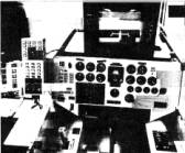
The HiMAT
RPV remote cockpit showing synthetic vision display.
Photo
courtesy of NASA.
[14] The Edwards Air Force
Base dry lake bed and runway were represented in three dimensions in the
terrain database as polygons (triangles and rectangles). An E&S Picture
System computer transformed the terrain in the database into a projected 3D
out-the-window view at the pilot cockpit. Finally, the projected 3D view was
displayed on an E&S Calligraphic video display system capable of 4000 lines
of resolution. According to the pilots participating in the study, the synthetic
vision compared well to the nose camera view. By the mid 1990s, NASA had
migrated the RPV synthetic vision concept used on HiMAT to PC computers for the
X-36 and X-38 flight demonstration vehicles.
[15] One of the early uses
of synthetic vision for UAVs-then most often called RPVs-was recreational
simulation. In 1986, Ambrosia Microcomputer Products of Willowbrook, Ill.,
introduced RC AeroChopper, a radio controlled aircraft simulator which enabled
pilots to learn to fly a remotely controlled aircraft, without risk to their
actual vehicle. According to the "AeroChopper Owner's Manual" (Stern,
1986), the product accepted aileron, elevator, rudder, and throttle pilot
inputs via joysticks to control the simulated aircraft. The product also
contained data files containing a 3D terrain database provided with AeroChopper
representing the earth's surface as well as buildings and obstructions.
[16] The software was run on
a computer (an Amiga for example) and was connected to the flight controls and
communicated the aircraft position and attitude to the user. The computer used
the terrain data to create a projected view of the aircraft and its environment
in three dimensions. Like most visual simulations of its time, the program used
relatively few polygons to represent the terrain and man-made objects and so
looks crude by today's standards.
Synthetic Vision for
Sensor Operations
[17] Although most of the
historical focus with synthetic vision has been on aiding flight management,
recent efforts have focused on how synthetic vision can aid UAS sensor operator
functions.
[18] Ongoing research at the
U.S. Air Force Research Laboratory's Human Effectiveness Directorate is
exploring how to improve the usefulness of video imagery to UAS sensor
operators. The overall objective is to determine the value of combining
synthetic vision imagery/symbology with live camera video presented on a UAS
control station camera display.
[19] One research study
evaluated the utility of computer-generated video overlays for four different
task types: controlling the camera to locate specific ground landmarks in the
360 degree area surrounding the loitering UAV; designating multiple ground
targets marked with synthetic symbology; tracing a synthetically highlighted
ground convoy route with the UAV camera boresight; and reading text from
synthetic overlaid symbology.
[20] The UAS telemetry
update rate was manipulated from 0.5 Hz to 24 Hz. The results indicated the
potential of synthetic symbology overlay for enhancing situation awareness,
reducing workload and improving the designation of points of interest at nearly
all the update rates evaluated and for all four task types. However, data
across the task types indicated that update rates greater than 2-4 Hz generally
resulted in improved objective performance and a subjective sense that the
symbology was useful.
[21] A second research area
focused on a picture-in-picture (PIP) concept where video imagery is surrounded
by a synthetic generated terrain imagery border on the physical camera display,
increasing the operator's instantaneous field-of-view. Experimental data showed
that the PIP helps mitigate the "soda-straw effect," reducing
landmark search time and enhancing operator situation awareness. In an
evaluation examining the impact of PIP display size and symbology overlay
registration errors, results indicated that performance on a landmark search
task was particularly better with the more compressed video imagery, reducing
average designation time by 60 percent. Also, the registration error between
the virtual flags and their respective physical correlates was less critical
with the PIP capability enabled. The details were published in
"Picture-in-Picture Augmentation of UAV Workstation Video Display" by
Gloria Calhoun and others in 2007.
[22] The recent availability
of sophisticated UAS autopilots capable of autonomous flight control has
fundamentally changed the paradigm of UAS operation, potentially reducing the
usefulness of synthetic vision for supporting UAS piloting tasks. At the same
time, research has demonstrated and quantified a substantial improvement in the
efficiency of sensor operations through the use of synthetic vision sensor
fusion technology. We expect this to continue to be an important technology for
UAS operation.
[23] Jeff Fox is Flight
Operations Engineer at NASA Johnson Space Center: Michael Abernathy is Director
of Development with Rapid Imaging Software, Inc. Mark Draper and Gloria Calhoun
are Senior Research Scientists at the Air Force Research Laboratory,
Wright-Patterson Air Force Base, Ohio.