by Jed Margolin
In the old days, whenever they showed an engineer working, there was usually an oscilloscope nearby with a pattern on the screen. Most often, the pattern was a Lissajous Figure.
Jules Antoine Lissajous (1822-1880) was a French physicist who was interested in waves, and around 1855 developed a method for displaying them optically by reflecting a light beam from a mirror attached to a vibrating object such as a tuning fork.
You might wonder why he didn't just use an oscilloscope. It was probably because the Cathode Ray Tube hadn't been invented yet. (It was invented in 1897 by Karl Ferdinand Braun).
A Lissajous figure is produced by taking two sine waves and displaying them at right angles to each other. This is easily done on an oscilloscope in XY mode.
In the following examples the two sine waves have equal amplitudes.
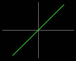
When the two sine waves are of equal frequency and in-phase, you get
a diagonal line to the right .
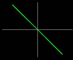
When the two sine waves are of equal frequency and 180 degrees out-of-phase
you get a diagonal line to the left.
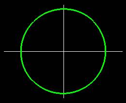
When the two sine waves are of equal frequency and 90 degrees out-of-phase
you get a circle.
This should not be a big surprise, because when
X = sin(a) and Y = sin(a + 90) = cos(a)
X*X + Y*Y = sin(a) * sin(a) + cos(a) * cos(a) = 1
which is the parametric equation for a circle having a radius of 1.
If the two sine waves are in phase but the frequency of the horizontal
sine wave is twice the frequency of the vertical sine wave you get the
pattern shown here.
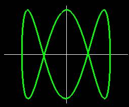
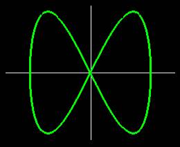
This shows the sine wave 90 degrees out-of-phase with the frequency
of the horizontal sine wave three times the frequency of the vertical sine
wave.
Mere static pictures do not do justice to Lissajous Figures.
When the horizontal and vertical sine wave frequencies differ by a fixed amount, this is equivalent to constantly rotating the phase between them.
The figure produced by this rotating phase appears to be a rotating 3D figure.
In addition, as in 3D wireframe images, the figure can appear to rotate in either direction, depending on how your brain interprets it. It can also spontaneously reverse the direction of rotation. (In a real 3D wireframe image the image can also appear to rotate around a different axis.)
The rotation of Lissajous Figures is something you need to see, so I am posting a program to do this.
Because the sine function is computationally intensive, the program starts out by calculating a table of sine values for a complete cycle of 360 degrees. Changing the address at which the table lookup is begun produces a sine wave with a different phase. The table address is wrapped so that the value is always valid.
By constantly increasing or decreasing the phase we produce the equivalent of having a small frequency difference. Technically, this is phase modulation. Large differences in frequency to produce integer multiples of frequencies are produced by multiplying the step size of the angles used to look up the sine value.
It is part of a program of Monitor Test Patterns that also produces Color Bars, a Crosshatch Pattern, a Dot Pattern, and a Monitor High Voltage Test.
The Color Bars are used to evaluate how well the Monitor reproduces colors.
The Crosshatch and Dot patterns are used to evaluate and adjust monitor convergence. (Don't try to adjust monitor convergence unless you know what you're doing and you have an enormous amount of patience.)
The Crosshatch pattern is also used to evaluate Geometric Distortion
in the Monitor.
A Monitor should produce a crosshatch pattern with nice regular squares.
A distorted pattern means either something is wrong or you have a crappy
monitor. I once had a moderately expensive Sony TV (not a computer monitor)
that exhibited noticeable geometric distortion. When I brought it to the
Sony Service Center they gave me quite a run-around. It finally came down
to:
Sony: This TV meets all of our specifications
for Geometric Distortion.
Me: I would like a copy of
your specifications for Geometric Distortion.
Sony: We have no specifications for Geometric
Distortion.
Eventually, they saw the wisdom of buying the TV back from me. (I bought an inexpensive Daytron Korean TV that was my primary TV for many years and still works even now.)
The High Voltage Test changes the screen brightness in order to see how well the High Voltage is regulated. When the High Voltage changes, so does the deflection sensitivity. (See my article on The Secret Life of XY Monitors if you would like an explanation.) When you are watching a TV program, it is really annoying to have the picture noticeably change size when the brightness of the scene changes. I have a newer model Magnavox TV whose High Voltage regulation sucks. I am betting on Organic LED (OLED) Displays to finally allow me to have an affordable flat panel TV with none of the design compromises that make TVs with CRTs so annoying.
I have done two versions of the program:
Version 1 uses OpenGL. It was compiled by Microsoft Visual C++ 6.0 and runs under Windows 9X. Support for OpenGL is built into Windows 9X. You don't have to install anything or screw around with the Operating System. All you do is run the program.
There are two versions of the Lissajous Patterns: one for fast machines and one for slow machines. The reason for this is that the Timer functions available in Windows are pathetic. The fastest you can get (without special gyrations) is 50 ms. Incredibly, there appears to be no way of determining when Vertical Retrace occurs, which is the best time for switching the display buffers.
My preference is that you examine the code until you understand it, then compile it yourself before running it. (Visual C++ 6.0 contains the OpenGL files you need to compile the program.)
This is my first real Windows program. I adapted the framework for the program from Jeff Molofee's excellent OpenGL tutorial available at www.nehe.gamedev.net/opengl.asp .
The framework is in Mtest.cpp . Any bugs are probably mine.
My part of the program is in Mprog.cpp . Any bugs are definitely mine.
If you do not have Visual C++, I suggest you run a virus checker on Mtest.exe before you run it. It will give us both some piece of mind.
Given the problems with viruses these days, I also suggest you download
it only from my Web site (www.jmargolin.com).
|
|
It should consist of the following files:
Name
Modified Size
Ratio Packed Path
Mprog.cpp 5/21/01
7:27 PM 29,487 82%
5,291
Mprog.h 5/21/01
7:29 PM 3,401 64%
1,236
Mtest.aps 5/13/01
1:29 PM 4,096 70%
1,215
Mtest.cpp 5/21/01
7:27 PM 17,992 66%
6,180
Mtest.dsp 5/17/01
10:39 AM 4,643 74%
1,200
Mtest.dsw 5/13/01
1 18 PM 533
61% 210
Mtest.exe 5/21/01
7:29 PM 53,248 57%
22,801
Mtest. h 5/13/01
1 17 PM 323
51% 157
Mtest. ico 5/13/01
1:17 PM 1,078 83%
180
Mtest. ncb 5/21/01
7:32 PM 66,560 85%
10,299
Mtest.opt 5/21/01
7:32 PM 53,760 92%
4,357
Mtest. plg 5/21/01
7:29 PM 6,154 86%
880
Mtest. rc 5/13/01
1:17 PM 3,056 70%
931
Readme.txt 5/13/01
1 17 PM 2,055 64%
741
Resource.h 5/13/01
1 17 PM 777
54% 357
Small.ico 5/13/01
1 17 PM 318
71% 91
Stdafx.cpp 5/13/01
1 17 PM 292
34% 192
Stdafx. h 5/13/01
1 17 PM 936
49% 476
18 file(s)
248,709 77% 56,794
Version 2 of the program is from the original DOS version that I developed using Borland Turbo C, which was a good way to learn C. Borland Turbo C has a nice Integrated Development Environment (IDE) but it is very forgiving and allows one to develop sloppy programming habits. Its main drawback is that the best it can produce is 286 code.
The version I am making available here has been updated somewhat. Mtest386.exe was compiled under Borland C 4.5 as a DOS program to produce 386 code. Mtest286.exe was compiled under Borland Turbo C to produce 286 code.
You can even put it on a boot disk.
I could have had the compiler produce 486 code but if you have an old
286 or 386 machine around you can keep the Lissajous Pattern running on
it so people will know you are a real engineer.
|
|
It should consist of the following files:
Name
Modified
Size Ratio Packed
Chatch.c 12/10/98
9:27 PM 8,137 83%
1,386
Colors.c 12/9/98
8:58 PM 6,357 80%
1,271
Colors.h 12/7/98
12:24 AM 1,750 67%
578
Main.c 5/21/01
8:04 PM 6,697 71%
1,960
Msine.c 5/21/01
11:34 PM 5,334 66%
1,827
Msine2.c 5/19/01
10:36 AM 4,417 68%
1,406
Mtable.h 5/19/01
10:50 AM 2,508 64%
892
Mtest286.exe 5/21/01 11:34 PM
81,715 43% 46,700
Mtest386.exe 5/21/01 11:44 AM
118,974 48% 62,410
9 file(s) 235,889 50% 118,430
Before there were frequency counters and phase locked loops, Lissajous Figures were used to compare two frequencies (such as a reference signal to an unknown signal) that were within a few integer multiples apart. You could even get a rough estimation of the phase between the signals.
Even today, there is value in taking the two channels of a stereo audio signal and connecting them to an oscilloscope in XY mode, especially if you are an FM Broadcast Station.
Not everyone who listens to an FM Station is listening in stereo; it is essential to produce a compatible monaural signal. (The process by which an FM Stereo signal is produced creates a monaural signal that is the sum of the Left and Right Channels.)
If, somewhere along the audio chain, the phase of one of channels is reversed, instead of getting a L+R signal, a monaural listener will hear the L-R channel. Since most announcers are placed in the center channel (L=R), the announcer will disappear.
This can go completely unnoticed by operators listening with a pair of stereo monitors.(The stereo image will be screwed up as well, but is easily missed in the pressure of a broadcast operation).
Connecting the Left and Right channels to an oscilloscope in XY mode will give an instant indication of the phases between the channels, since much of the material in a stereo signal is in-phase. If, when the announcer comes on, you see a 45 degree line to the right (as in the first figure in this article) you are ok. If you get a 45 degree line to the left (as in the second figure) one of your channels is out of phase. It's easy to make that kind of error when wiring a radio station. I heard one FM station broadcast for the first several hours of its first day on the air with a channel out of phase. (No, it wasn't my station.) I called them up but the operator on duty didn't know what I was talking about.)
It might be interesting to program a PC to take the inputs from the sound card and display them on the screen in XY mode. Then connect the channels to an stereo FM radio and tune across the dial.
It might also be interesting to program Lissajous figures and play them through the sound card.
And, finally, even today with all the sophisticated graphics that people do, Lissajous Figures are still compelling to look at.
Run the program in full-screen mode with the lights out and you will
see why.
Jed Margolin
San Jose, CA
May 23, 2001
Copyright 2001 Jed Margolin
|
|