Synthetic Vision Technology for Unmanned Aerial Systems: The Real
Story
By Jed Margolin
January 8, 2009
(Abridged)
This is in response to
the article Synthetic Vision Technology for Unmanned Systems: Looking Back
and Looking Forward by Jeff Fox, Michael Abernathy, Mark Draper and Gloria
Calhoun which appeared in the December 2008 issue of AUVSI’s Unmanned Systems
(page 27). {Ref. 1}
The AUVSI Authors have
used the term “synthetic vision” so loosely that many readers will believe it
was invented long before it actually was. This is an important issue. Aerospace
is a field where precision and accuracy is critical. There are also patent
rights involved. In the interests of full disclosure I am the listed inventor on
several patents relating to synthetic vision and there is a patent infringement
disagreement between the owner of the patents (Optima Technology Group) and the
company that one of the AUVSI Authors is affiliated with (Rapid Imaging
Software).
What Is Synthetic Vision?
The term “Synthetic
Vision” originally meant anything that you put up on a video display.
For example, there is
U.S. Patent 5,593,114 Synthetic Vision Automatic Landing System issued
January 14, 1997 to Ruhl (Assignee McDonnell Douglas Corporation) where Enhanced
or Synthetic Vision is a display of the data from a forward looking radar or
equivalent sensor. {Ref. 2 - Column 2, lines 16 -
27}
This was also the FAA’s
definition at the time, in their Synthetic Vision Technology
Demonstration, Volume 1 of 4, Executive Summary (Ref 3 - PDF page 10 and PDF pages 11,12}
In the AUVSI Authors’
own article they equate “pictorial format avionics” with “synthetic
vision.” [Paragraph 10]:
Pictorial format avionics
(i.e., synthetic vision) formed a key ingredient of the Air Force Super Cockpit
concept.
Boeing’s report Multi-Crew
Pictorial Format Display Evaluation describes what Pictorial Format means. {Ref. 4 - PDF Page 17}:
In the first of the two PFDE
studies, pictorial formats were implemented and evaluated for flight, tactical
situation, system status, engine status, stores management, and emergency
status displays. The second PFDE study concentrated on the depiction of threat
data.
Pictorial Format
Avionics is pictures. That explains why it is called Pictorial
Format Avionics.
Why can’t we use the
term “Synthetic Vision” to mean anything we want it to mean?
The FAA has a definition
for “Synthetic Vision” and if you want an FAA type certificate for your
Synthetic Vision product you have to use their definition.
{Ref. 5 – FAA current definition of synthetic
vision}
Synthetic vision means a computer-generated image of the external scene topography from the perspective of the flight deck that is derived from aircraft attitude, high-precision navigation solution, and database of terrain, obstacles and relevant cultural features.
{Ref. 6 – FAA Synthetic
Vision is based on a Digital Elevation Database}
“Everyone gets their data from the same original source.”
“If accuracy of data base must be validated then SV is unapproveable.”
“Current resolution tends to round-up the elevation data so
that small errors are not as significant and on the conservative side.”
Therefore, Synthetic
Vision means a computer-generated image of the external scene topography from
the perspective of the flight deck that is derived from aircraft attitude,
high-precision navigation solution, and digital terrain elevation database,
obstacles and relevant cultural features.
Implicit in this is that
in order for the external scene topography to be viewed from the perspective of
the flight deck it has to be a 3D projected view and that the digital terrain
elevation database must represent real terrestrial terrain, as opposed to
terrain that is simply made up.
Digital Terrain Elevation Database
The Digital Terrain Elevation Database is also called
the Digital Elevation Database or Digital Elevation Model. From Ref. 7:
The USGS Digital Elevation Model (DEM) data files are digital
representations of cartographic information in a raster form. DEMs consist of a
sampled array of elevations for a number of ground positions at regularly
spaced intervals. These digital cartographic/geographic data files are produced
by the U.S. Geological Survey (USGS) as part of the National Mapping Program
and are sold in 7.5-minute, 15-minute, 2-arc-second (also known as 30-minute),
and 1-degree units. The 7.5- and 15-minute DEMs are included in the large scale
category while 2-arc-second DEMs fall within the intermediate scale category
and 1-degree DEMs fall within the small scale category - (Source: USGS)
The Digital Elevation
Model was substantially improved by STS-99 when Endeavour's international
crew of seven spent 11 days in orbit during February 2000 mapping the Earth's
surface with radar instruments. {Ref. 8}
Displaying
the Digital Elevation Database
Now that
we have a Digital Elevation Database consisting of a sampled array of
elevations for a number of ground positions at regularly spaced intervals, what
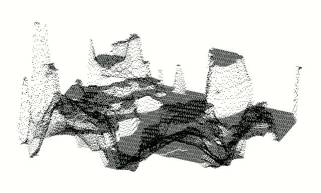
do we do with it? The database is just elevation points.
If you display only points there is no way to remove
"hidden points" because there are no surfaces to test them against.
(Things can only be hidden behind surfaces.) The result is a jumble
which looks like this (the only useful features are the highest peaks):
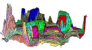
This picture shows the same scene rendered in polygons.
(The polygons are crude because I had only a few colors to work with and there
is no clipping, only polygon sorting):
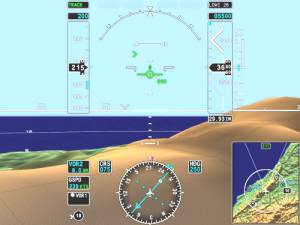
After you have used the
digital elevation points to produce polygons you can shade and blend the
polygons so that the underlying polygons may no longer be obvious. Honeywell
did an excellent job in their IPFD (Instrument Primary Flight Display) {Ref. 9}:
NASA
HiMAT
The AUVSI Authors have
gone to considerable lengths to persuade readers that NASA’s HiMAT project was
Synthetic Vision [Paragraphs 11 – 14]. It wasn’t.
From Sarrafian (Ref. 11}
1. "The vehicle was flown
with cockpit display instruments until the landing approach phase of the flight
when the camera aboard the aircraft was activated to provide the pilot with a
television display during the approach."
2. During the operational phase of the HiMAT program, a
simulator was used to adjust the control laws for the primary control system.
The display presented to the pilot of this simulated system was a display
of an instrument landing system (ILS).
3. Separately, a study was undertaken to compare
evaluations of pilots using a simulated visual display of the runway scene
and a simulated ILS display with the results of actual flight tests,
using the HiMAT aircraft as a representative remotely piloted research vehicle.
There is no mention of a terrain database or any suggestion that the simulated
visual display of the runway scene was ever used to control a real aircraft. It
was never anything other than a simulation.
From
NASA's description of the HiMAT project {Ref. 10}:
Highly Maneuverable Aircraft Technology
From mid-1979 to January 1983, two remotely piloted, experimental Highly Maneuverable Aircraft Technology (HiMAT) vehicles were used at the NASA Dryden Flight Research Center at Edwards, Calif., to develop high-performance fighter technologies that would be applied to later aircraft. Each aircraft was approximately half the size of an F-16 and had nearly twice the fighter's turning capability.
and,
later:
The small aircraft were launched from NASA's B-52 carrier plane at an altitude of approximately 45,000 feet. Each HiMAT plane had a digital on-board computer system and was flown remotely by a NASA research pilot from a ground station with the aid of a television camera mounted in the cockpit. There was also a TF-104G chase aircraft with backup controls if the remote pilot lost ground control.
NASA's
article says it was flown remotely by a pilot using a television camera in
the aircraft. It does not say it was flown using what is now known as synthetic
vision. (As previously explained, the definition of the term "synthetic
vision" has changed over the years.)
The AUVSI Authors cite the report by Shahan Sarrafian,"Simulator
Evaluation of a Remotely Piloted Vehicle Lateral Landing Task Using a Visual
Display." There are two
Sarrafian reports with that title, one dated May 1984; the other dated August
1984. See Ref. 11 which contains links to the reports
as well as to mirrored copies. The August 1984 report has been converted to
text to make it easy to search and to quote from.
The title of the Sarrafian report gives an accurate description of his project,
"Simulator Evaluation of a Remotely Piloted Vehicle Lateral Landing
Task Using a Visual Display."
There is no mention of a terrain database or any suggestion that the simulated
visual display of the runway scene was ever used to control a real aircraft. It
was never anything other than a simulation.
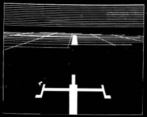
The
following is a picture of the image Sarrafian produced in his simulator (Figure
9 - Simulated landing approach conditions on glideslope):
The display was created with an Evans and Sutherland
Picture System {Ref. 16} using a calligraphic monitor. The term calligraphic
means that the system only drew lines and dots. This type of system is also
called Random Scan because the electron beam in the CRT can be
moved anywhere on the screen, as opposed to a Raster Scan system, which draws a
raster. Atari's term for Random Scan was XY or Vector and
was used in several games in the late 1970s and early 1980s such as Asteroids,
BattleZone, and Star Wars.
The solid areas are filled-in by drawing lots of lines.
The lines above the horizon are presumably meant to indicate the sky. The grid
lines are presumably meant to indicate the ground. There is no suggestion that
the grid lines are produced from a digital elevation database. There would be
no reason to use a digital elevation database because the system was used only
to simulate landings. (Indeed, the name of the study is "Simulator
Evaluation of a Remotely Piloted Vehicle Lateral Landing Task Using
a Visual Display.")
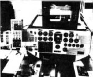
The AUVSI Authors have reproduced a picture in their
article with the caption, “The HiMAT RPV remote cockpit showing synthetic vision
display. Photo
courtesy of NASA.”
This picture is identical to the picture in Sarrafian
Figure 5 {Ref. 11},
August 1984, PDF page 10} but the Sarrafian picture has a different caption. It
says, “ HiMAT simulation cockpit.”
|
The HiMAT RPV remote cockpit showing synthetic vision display. Photo
courtesy of NASA. |
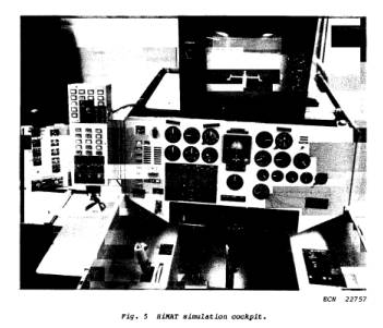 |
The monitor shows a picture of the kind shown in Sarrafian
Figure 8 or Figure 9 (along with a considerable amount of what appears to be
reflected glare). The picture was produced by an Evans and Sutherland Picture System which requires a
calligraphic monitor.
Here’s the thing. "The vehicle was flown with cockpit
display instruments until the landing approach phase of the flight when the
camera aboard the aircraft was activated to provide the pilot with a television
display during the approach."
In order to display the video from the camera aboard the
aircraft, the Ground Cockpit that controlled the aircraft had to have a
raster-scan monitor.
Raster-scan monitors and Calligraphic monitors are
incompatible.
The picture shows the Simulation Cockpit, and the
Simulation Cockpit could not be used to control the aircraft.
Why did the AUVSI Authors change the caption?
Visual-Proprioceptive Cue Conflicts in the Control of
Remotely Piloted Vehicles, Reed, 1977
In paragraph 9 the AUVSI Authors state:
Also in 1979, the Air Force published research identifying
human factors problems that would have to be overcome in RPV cockpit design
("Visual- Proprioceptive Cue Conflicts in the Control of Remotely Piloted
Vehicles" by Reed in 1977). NASA would use this in the design of the HiMAT RPV
3D visual system in 1984.
Ref. 14 provides the link to the Reed report.
This is what the Reed report was about. From page 5 (PDF page 8):
An operator is asked to maneuver a remotely piloted vehicle
(RPV) from an airborne control station (a mother ship). This station is equipped with a television monitor,
control stick, and other controls and displays necessary to maneuver the RPV
through a specified course. The RPV, containing a television camera mounted in
its nose, relays an image of the terrain to be displayed on the television
monitor in the control station. Thus, the visual scene displayed to the operator
represents the scene viewed by the camera. The task of the operator is to use
the controls and displays to "fly" the RPV in much the same way he would fly a
conventional aircraft.
And from page 7 (PDF page 10):
Visual
system. The visual system consisted of a three-dimensional terrain model (a
modified SMK-23 Visual Simulator, The Singer
Company), television camera and optical probe, and
three monochromatic television monitors. The terrain
model provided “real-world ground cues for visual tracking over the surface.
The real-world to terrain model scale was 3,000:1 and represented a six by
twelve-mile (9.65 by 19.3 km) area. The model was
mounted on an endless belt that was servo-driven to represent the continuous
changes in scene as the simulated RPV traveled along north-south directions. A
television camera viewed the terrain model through an optical probe that
contained a servoed mechanical assembly to permit the introductions of heading,
roll, and pitch. Both the camera and probe were mounted on a servo-driven
carriage system that moved across the terrain model to simulate movement of the
RPV along east-west directions and in and out to simulate altitude changes.
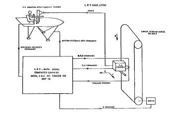
The SMK-23 was also used in The Lunar Roving Vehicle (LRV)
simulator {Ref. 15}. This shows what an SMK-23 looks
like.
The SMK-23 used a television camera with an optical probe
to fly over the terrain model contained on a servo-driven endless belt.
If Reed had had synthetic
vision why would he have used the SMK-23 mechanical contraption?
The only link between Reed and HiMAT is that the HiMAT
aircraft could be landed by either a ground-based pilot or an airborne
controller (the backseat chase pilot in the TF-104G aircraft). While HiMAT might
have used the results of the Reed report to select the airborne controller (the
backseat chase pilot in the TF-104G aircraft) Reed did not use synthetic vision
and neither did HiMAT.
Simulators
The AUVSI Authors describe several flight simulators, such
as the RC AeroChopper by Ambrosia Microcomputer Products [Paragraphs 15 and 16]
and Bruce Artwick’s “Flight Simulator” for the Apple II, which ultimately became
Microsoft Flight Simulator. [Paragraph 5]
RC AeroChopper was developed by David R. Stern at Ambrosia
Microcomputer Products. The following is from an email correspondence with Mr.
Stern:
Question 1: Did AeroChopper use a 3D terrain database?
Mr.
Stern: I guess
it did, although the ground was a plane with 3D objects (and a 2D runway)
scattered around (trees, pylon, towers with crossbar to fly under).
Question 2: If
so, did it represent real terrestrial terrain?
Mr.
Stern: No.
RC AeroChopper was a significant achievement for the home
computers available at the time and was a highly regarded simulator {Ref. 17} but:
1. It did not use a digital elevation database;
“... the ground was a plane with 3D objects (and a 2D runway)
scattered around (trees, pylon, towers with crossbar to fly under),” and thus,
did not represent real terrestrial terrain.
2. It did not provide a computer-generated image of the external scene topography from the perspective of the
flight deck that is derived from aircraft attitude,
high-precision navigation solution, and database of terrain, obstacles and
relevant cultural features.
It was not synthetic vision. It was a simulator.
Now, let’s discuss Microsoft Flight Simulator {Ref. 18}. Flight Simulator 5.1 was released in
1995. Microsoft Flight Simulator did not start using 3D terrain until Flight
Simulator 2000 Pro, released in late 1999 {Ref. 19}. Even
then, it is not clear if the terrain database represents real terrain or is made
up.
The article mentions the
new GPS feature which is part of the simulated 737 control panel. There is no
suggestion that a physical GPS unit can be connected to the program.
A simulator is not synthetic vision. A simulator might do a
good job simulating synthetic vision. It might even use a Digital Terrain
Elevation Database representing real terrestrial terrain, but that does not make
it synthetic vision. It is a simulator. If it does not control a physical
aircraft it is not synthetic vision.
When Did NASA Start Working on Synthetic Vision?
From Ref 20:
Synthetic Vision Could Help General Aviation Pilots Steer Clear
of Fatalities
Hampton,
Virginia -- Research
Triangle Institute and six companies are teaming up to develop revolutionary new
general
aviation cockpit displays to give pilots clear views of their surroundings in bad
weather and darkness.
See Ref. 20 for the remainder of the news release and
Ref. 21 for NASA’s news release.
When did NASA first use synthetic vision to control a
UAV?
It was in the X-38 project. See Ref 22:
"Virtual Cockpit Window" for a Windowless Aerospacecraft
from the January 2003 issue of NASA Tech Briefs.
The Press Release from Rapid Imaging Software, Inc., which did the synthetic
vision work for the X-38, states {Ref. 23}
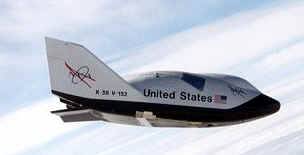
On December 13th, 2001, Astronaut Ken Ham successfully flew
the X-38 from a remote cockpit using LandForm VisualFlight as his primary
situation awareness display in a flight test at Edwards Air Force Base,
California. This simulates conditions of a real flight for the windowless
spacecraft, which will eventually become NASA's Crew Return Vehicle for the ISS.
We believe that this is the first test of a hybrid synthetic vision system which
combines nose camera video with a LandForm synthetic vision display. Described
by astronauts as "the best seat in the house", the system will ultimately make
space travel safer by providing situation awareness during the landing phase of
flight.
Other References cited by the AUVSI Authors
"Pathway-in-the-Sky Contact Analog Piloting Display," Knox
and Leavitt, 1977
In the article the AUVSI Authors state in Paragraph 7:
In 1977, NASA researcher Charles Knox published "Pathway-in-the-Sky Contact Analog Piloting Display," which included a complete design for a synthetic vision system. It featured a computer that projected a 3D view of the terrain given an aircraft's position and orientation. This out-the-window perspective view was displayed on a CRT type display. Such displays were called "Pictorial Format" avionics systems, but we recognize them as containing all of the essential elements of a modern synthetic vision display.
The
complete Knox report is Ref.
24.
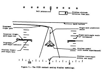
Everything comes together in Knox Figure 4, which shows the
Airplane track-angle pointer and scale, the Airplane symbol with shadow
superimposed, the Flight-path-angle scale, the Flight-path prediction vector,
the Earth horizon, the Roll pointer, the Airplane altitude deviation from path,
the Airplane flight-angle bars, the Programmed path-angle indicator, the
Potential flight-path-angle box, and the Programmed flight path.
The Programmed flight-path consists of two
three-dimensional lines showing the predicted flight path of the airplane. Knox
and Leavitt’s work is significant but there is no terrain, there is no digital
elevation database. There is no synthetic vision.
“The Electronic Terrain Map: A New Avionics
Integrator", Small, D.M., 1981 {Ref 25}
In the article the AUVSI Authors state in Paragraph 8:
In 1979, the U.S. Air Force completed its "Airborne
Electronic Terrain Map Applications Study" and in 1981 published "The Electronic
Terrain Map: A New Avionics Integrator" describing how a computerized terrain
database could be displayed as an out-the-window 3D view allowing the pilot to
"see" even at night and in other limited visibility situations.
No, Small did not describe “how a computerized terrain
database could be displayed as an out-the-window 3D view allowing the pilot to
‘see’ even at night and in other limited visibility situations.”
The Small report discusses the concept of a digital
Electronic Terrain Map (ETM) and proposes that it be used for Navigation;
Terrain Following/Terrain Avoidance (TF/TA); Threat avoidance, analysis,
warning, and display; Terrain Masking; Weapon delivery; and Route planning.
For Navigation Small gives a choice between Radar-scanned
terrain and finding your location on a map using an undefined method of
adding a correlator to the avionic suite and using the on-board
sensors together with the Electronic Terrain Map (ETM).
Small’s failure to mention omission of Terrain Referenced
Navigation and Tercom is puzzling since both existed at the time he write the
report.
He does say, “An electronic map subsystem can generate
perspective scenes, which are essentially computer generated images of the
surrounding area, and an electronic map should be much easier to interpret,” but
the statement must be understood according to the meaning it would have had at
the time the article was written (circa 1981) and wishing for a desired result
is not the same as teaching how to do it.
In the 1980s (and well into the 1990s) the conventional
wisdom was that Real 3D graphics was too computationally intensive to do in real
time without large and very expensive hardware.
Honeywell was the leader in avionics. Harris was probably a
close second. They both spent the 1980s and 1990s competing with each other to
see who could do the best fake 3D.
There is Honeywell’s U.S. Patent 5,179,638 Method and apparatus for generating a texture mapped
perspective view issued January 12, 1993 to Dawson, et al. (Ref. 32}
It even has the word “perspective” in the title, but the
perspective it produces is a trapezoidal perspective, not a real 3D projected
perspective.
A real 3D perspective is a 3D projection.
Anything else is Fake 3D.
If you think Fake 3D is just as good as Real 3D then the
next time someone owes you money tell them that it’s ok to pay you in fake
dollars.
There is also the matter that Small is only wishing for a
desired result. Wishing for a desired result is not the same as teaching how to
do it.
Not only did Small not teach it, he was not clear in saying what he was wishing for.
VCASS: An Approach to Visual Simulation, Kocian, D., 1977
In the article the AUVSI Authors state in Paragraph 6:
This emergence of computer flight simulation in the 1970s
appears to have sparked a monumental amount of research. The U.S. Air Force
began its Visually Coupled Airborne Systems Simulator (VCASS) program, with a
particular eye toward future-generation fighter aircraft ("VCASS: An Approach to
Visual Simulation," Kocian, D., 1977).
The Kocian report is available in Ref. 34.
Kocian is about using a Helmut Mounted Display (HMD) with a
Head Position Sensing System to replace large expensive hemispherical display
systems used in simulators. The simulator is used to develop the visual
interface used by crew members to control advanced weapon systems. This visual
interface can then be used in airborne operations.
During simulation a representative visual scene is
generated by the graphics or sensor imagery generators but, from Paragraph 11:
For an airborne VCASS capability, it is only necessary to
install the VCS components along with a small airborne general purpose computer
in a suitable aircraft and interface a representative programmable symbol generator to an on-board attitude reference
system in order to synthesize either airborne or ground
targets.
The airborne version does not synthesize a visual scene, so
it is not synthetic vision.
U.S. Patent 5,566,073 Pilot Aid Using A Synthetic Environment issued October
15, 1996 to Margolin
This patent was not mentioned by the AUVSI Authors.
Abstract
A pilot aid using synthetic reality consists of a way to determine the aircraft's position and attitude such as by the global positioning system (GPS), a digital data base containing three-dimensional polygon data for terrain and manmade structures, a computer, and a display. The computer uses the aircraft's position and attitude to look up the terrain and manmade structure data in the data base and by using standard computer graphics methods creates a projected three-dimensional scene on a cockpit display. This presents the pilot with a synthesized view of the world regardless of the actual visibility. A second embodiment uses a head-mounted display with a head position sensor to provide the pilot with a synthesized view of the world that responds to where he or she is looking and which is not blocked by the cockpit or other aircraft structures. A third embodiment allows the pilot to preview the route ahead or to replay previous flights.
It teaches what is now known as synthetic vision in
sufficient detail that it may be practiced by a Person
having Ordinary Skill In The Art without undue experimentation. A Person
having Ordinary Skill In The Art (POSITA) is a legal term that is often fought
over during patent litigation.
This patent is a continuation of Application Ser. No.
08/274,394, filed Jul. 11, 1994, which is its filing priority date. The earliest
known description of the invention is in Ref. 35.
For those unfamiliar with Patent Law, the Claims are the
legal definition of the invention. The purpose of the Abstract is to provide
search terms only.
See Ref. 36 for the patent. (I am
the inventor named in the patent.)
U.S. Patent 5,904,724 Method and apparatus for remotely piloting an aircraft
issued May 18, 1999 to Margolin
This patent was also not mentioned by the AUVSI
Authors.
Abstract
A method and apparatus that allows a remote aircraft to be controlled by a remotely located pilot who is presented with a synthesized three-dimensional projected view representing the environment around the remote aircraft. According to one aspect of the invention, a remote aircraft transmits its three-dimensional position and orientation to a remote pilot station. The remote pilot station applies this information to a digital database containing a three dimensional description of the environment around the remote aircraft to present the remote pilot with a three dimensional projected view of this environment. The remote pilot reacts to this view and interacts with the pilot controls, whose signals are transmitted back to the remote aircraft. In addition, the system compensates for the communications delay between the remote aircraft and the remote pilot station by controlling the sensitivity of the pilot controls.
It teaches the use of synthetic vision (as the term is
currently used) for remotely piloting an aircraft. It teaches it in sufficient
detail that it may be practiced by a Person having Ordinary Skill In The Art
without undue experimentation.
This patent was filed January 19, 1996, which is its
priority date.
For those unfamiliar with Patent Law, the Claims are the
legal definition of the invention. The purpose of the Abstract is to provide
search terms only.
See Ref. 37 for the patent. (I am
the inventor named in the patent.)
U.S. Patent Application Publication 20080033604 System and Method For Safely Flying Unmanned Aerial
Vehicles in Civilian Airspace
In the interests of full disclosure I have the following
patent application pending: U.S. Patent Application Publication 20080033604 System and Method For Safely Flying Unmanned Aerial
Vehicles in Civilian Airspace.
Abstract
A system and method for safely flying an unmanned aerial vehicle (UAV), unmanned combat aerial vehicle (UCAV), or remotely piloted vehicle (RPV) in civilian airspace uses a remotely located pilot to control the aircraft using a synthetic vision system during at least selected phases of the flight such as during take-offs and landings.
See Ref. 38 for the published patent application. (I am the inventor named in the application)
The Future of Synthetic Vision
This is what the AUVSI Authors have said about synthetic
vision [Paragraph 2]:
More recently it has evolved away from being a piloting aid
to a potentially powerful tool for sensor operators.
and [Paragraph 22]:
The recent availability of
sophisticated UAS autopilots capable of autonomous flight control has
fundamentally changed the paradigm of UAS operation, potentially reducing the
usefulness of synthetic vision for supporting UAS piloting tasks. At the same
time, research has demonstrated and quantified a substantial improvement in the
efficiency of sensor operations through the use of synthetic vision sensor
fusion technology. We expect this to continue to be an important technology for
UAS operation.
While I have no doubt that synthetic vision is very useful
to the sensor operator, the news that its use in piloting UAVs is on its way out
came as a big surprise to me.
The AUVSI Authors have an ulterior motive in making the
statements. Their real objective is to make people believe synthetic vision no
longer has value in controlling Remotely Piloted Vehicles (aka UAVs) and that a
Remotely Piloted Vehicle that is flown using an Autonomous control system is no
longer a remotely piloted vehicle and therefore a
sensor operator may use synthetic vision without infringing U.S. Patent
5,904,724. See Ref. 39 for the response Rapid Imaging Software’s
attorney sent to Optima Technology Group in 2006.
The statements made by the AUVSI Authors form a distinction
without a difference unless there is a wall between the sensor operator and the
pilot that results in the sensor operator having no influence on how or where
the UAV is flown, regardless of whether it is flown with a human pilot or a
machine pilot.
There are legal and political ramifications to this.
Someone has to be responsible for the operation and safety
of the flight. The FAA defines “Pilot in Command” as {Ref. 5}:
Pilot in command means the person who:
(1) Has final authority and responsibility for
the operation and safety of the flight;
(2) Has been designated as pilot in command
before or during the flight; and
(3) Holds the appropriate category, class, and
type rating, if appropriate, for the conduct of the flight.
It is unlikely that FAA will allow this responsibility to
be delegated to a machine anytime soon. That’s where the political ramifications
come in. A UAV (especially a completely autonomous UAV) that injures
or kills civilians would ignite a political firestorm that would ground the
entire UAV fleet.
Frankly, it is stupid to cripple the utility of a UAV
system in order to avoid paying a small patent licensing fee. Besides, the ‘724
patent is for the use of synthetic vision in a Remotely Piloted Aircraft. It is
not limited to the use of synthetic vision by the crew member designated as the
Pilot.
An autonomous pilot would have to be really good.
Even after 100 years of aviation, pilots still encounter
situations and problems that have not been seen before. The way they deal with
new situations and problems is to use their experience, judgment, and even
intuition. Pilots have been remarkably successful in saving passengers and crew
under extremely difficult conditions such as when parts of their aircraft fall
off (the top of the fuselage peels off) or multiply-redundant critical controls
fail (no rudder control). Computers cannot be programmed to display judgment.
They can only be programmed to display judgment-like behavior under conditions
that have already been anticipated. UAVs should not be allowed to fly over
people's houses until they are at least smart enough to turn on their own fuel
supply.
[ On Apr. 25, 2006 the Predator UAV being used by the U.S.
Customs and Border Protection agency to patrol the border crashed in Nogales,
Ariz. According to the NTSB report (NTSB Identification CHI06MA121) when the
remote pilot switched from one console to another the Predator was inadvertently
commanded to shut off its fuel supply and "With no engine power, the UAV
continued to descend below line-of-site communications and further attempts to
re-establish contact with the UAV were not successful." In other words, the
Predator crashed because the system did not warn the remote pilot he had turned
off the fuel supply and it was not smart enough to turn its fuel supply back on.
{Ref. 40} ]
An autonomous UAV assumes the computer program has no bugs.
Complex computer programs
always have bugs no matter how brilliant or motivated the programmer(s). As an
example, look at almost every computer program ever written.
An autonomous Unmanned Combat
Aerial Vehicle (UCAV) will have little chance against one flown by an
experienced pilot using Synthetic Vision until Artificial Intelligence produces
a sentient, conscious Being. At that point, all bets will be off because a
superior sentient artificial Being may decide that war is stupid and refuse to
participate. It may also decide that humans are obsolete or are fit only to be
its slaves.
I propose yearly fly-offs:
1. A UCAV flown and fought autonomously
against an F-22 (or F-35).
2. A UCAV flown and fought by a human
pilot using synthetic vision against an F-22 (or F-35).
3. A UCAV flown and fought by a human
pilot using synthetic vision against a UCAV flown and fought autonomously.
And that is the future of Unmanned Aerial Systems.
References
Reference 1 - Synthetic Vision Technology for Unmanned Systems: Looking
Back and Looking Forward by Jeff Fox, Michael Abernathy, Mark Draper and
Gloria Calhoun, AUVSI’s Unmanned Systems, December
2008, pages 27-28.
This article has been reproduced with the permission of the Association for Unmanned Vehicle Systems International (AUVSI), which is the world's largest non-profit organization devoted exclusively to advancing the unmanned systems community. AUVSI, with members from government organizations, industry and academia, is committed to fostering, developing, and promoting unmanned systems and related technologies. http://www.auvsi.org/
PDF: refs/ref01_auvsi.pdf
For the purposes of this response the article has been
converted to text and the paragraphs have been numbered for easy reference: refs/ref01_auvsi.htm
Reference 2 – U.S. Patent 5,593,114 Synthetic
Vision Automatic Landing System issued January 14, 1997 to Ruhl (Assignee
McDonnel Douglas Corporation).
Html copy at USPTO Patent Database:
PDF copy (complete with drawings): refs/ref02_5593114.pdf
Reference 3 - Synthetic Vision
Technology Demonstration, Volume 1 of 4, Executive Summary; Synthetic Vision
Program Office Federal Aviation Administration; Malcolm A. Burgess, FAA; Terence
Chang, TRW; Dale E. Dunford, USAF; Roger H. Hoh, Hoh Aeronautics; Walter F.
Home, GTRI; Richard F. Tucker, TRW; December 1993. http://www.dtic.mil/srch/doc?collection=t2&id=ADA280564
Mirrored Copy: refs/ref03_old_faa_1993.pdf
Reference 4 – Multi-Crew Pictorial Format
Display Evaluation; AFWAL-TR-87-3047;
T.C. Way, R.L. Martin, J.G. Gilmour, M.E. Hornsby, R.E.
Edwards; Final Report For Period May 1984 – January 1987, Boeing Military
Airplane Company, February 1987.
http://handle.dtic.mil/100.2/ADA189349
Mirrored copy: refs/ref04_pictorial_format.pdf
Reference 5 – FAA current
definition of Synthetic Vision - FAA Title 14 Part 1
The FAA definition of synthetic vision from: http://ecfr.gpoaccess.gov/cgi/t/text/text-idx?c=ecfr&sid=41b1c51ea8ec4c9d1c5ebb94bbf28138&rgn=div8&view=text&node=14:1.0.1.1.1.0.1.1&idno=14
Mirrored Copy: refs/ref05_faa.pdf
Reference 6 – FAA Synthetic Vision is based on the use of a Digital Elevation Database
Federal Aviation Administration Part 23 Synthetic Vision Approval Approach; Presentation to: FAA Synthetic Vision Workshop; Name: Lowell Foster; Date: Feb 14, 2006; FAA SV Issues- Part 23 Position
http://www.faa.gov/aircraft/air_cert/design_approvals/transport/media/Pt23ApproachSlides.pdf
Mirrored Copy: refs/ref06_Pt23ApproachSlides.pdf
Reference 7 – Digital Elevation Model: http://data.geocomm.com/dem/
Mirrored Copy: refs/ref07_usgs_dem.pdf
Reference 8 – Digital Elevation Database improved by a Space Shuttle
mission.
http://spaceflight.nasa.gov/shuttle/archives/sts-99/
Mirrored Copy: refs/ref08_sts99.pdf
Reference 9 – Honeywell IFPD Synthetic Vision System
http://www.honeywell.com/sites/portal?page=ipfd_primus&smap=aerospace&theme=T5
Mirrored Copy: refs/ref09_honeywell.pdf
Reference 10 - NASA description of the HiMAT project:
http://www.nasa.gov/centers/dryden/news/FactSheets/FS-025-DFRC.html
Mirrored Copy: refs/ref10_nasa_himat.pdf
Reference 11 - Simulator Evaluation of a Remotely Piloted Vehicle Lateral
Landing Task Using a Visual Display, Shahan K. Sarrafian
NASA Technical Memorandum 84916 (May 1984):
http://www.nasa.gov/centers/dryden/pdf/87968main_H-1205.pdf
NASA Technical Memorandum 85903 (August 1984):
http://www.nasa.gov/centers/dryden/pdf/87986main_H-1246.pdf
refs/ref11b_sarrafian.pdf
I converted this article to text
in order to make it easier to search and to quote from.
refs/ref11c_sarrafian.doc .
The downloaded PDF file is the controlling version.
Reference 12 - NASA Aviation Navigation
Tutorial: http://virtualskies.arc.nasa.gov/navigation/tutorial/tutorial3.html
Mirrored copy: refs/ref12_nasa_ils.pdf
Reference 13 – THE ROLE OF SIMULATION IN THE DEVELOPMENT AND FLIGHT TEST
OF THE HIMAT VEHICLE , M. B. Evans and L. J. Schilling, NASA-TM-84912, April
1984
http://www.nasa.gov/centers/dryden/pdf/87962main_H-1190.pdf
Mirrored Copy: refs/ref13_evans_schilling.pdf
Reference 14 - Visual-Proprioceptive Cue Conflicts in the Control of
Remotely Piloted Vehicles, Reed, 1977, AFHRL-TR-77-57
http://www.dtic.mil/srch/doc?collection=t2&id=ADA049706
http://handle.dtic.mil/100.2/ADA049706
Mirrored Copy: refs/ref14_reed.pdf
Reference 15 - Lunar Driving Simulator History
http://www.knology.net/~skeetv/SimHist3.html
Mirrored copy: refs/ref15_lunar_driving_history.pdf
Reference 16 - Evans & Sutherland Picture System:
Short Brochure: http://www.computerhistory.org/brochures/companies.php?alpha=d-f&company=com-42b9d8b7f4191
Full Brochure: http://archive.computerhistory.org/resources/text/Evans_Sutherland/EvansSutherland.3D.1974.102646288.pdf
Mirrored copy:
Short Brochure: refs/ref16_esps_s.pdf
Full Brochure: refs/ref16_esps_f.pdf
Reference 17 – RC AeroChopper Review: http://www.atarimagazines.com/startv3n9/rcaerochopper.html
Mirrored Copy: refs/ref17_aerochopper.pdf
Reference 18 – Microsoft Flight Simulator
Microsoft Flight Simulator 5.1 Screen Shot: refs/ref18_fs5_1_screenshot.pdf
Microsoft Flight Simulator History: refs/ref18_fs_history.pdf
Reference 19 – Microsoft Flight Simulator’s first use of terrain points:
http://www.flightsim.com/cgi/kds?$=main/review/fs2000.htm
Mirrored copy: refs/ref19_fs_first.pdf
Reference 20 – News releases from RTI (Research Triangle Institute),
Avidyne, AvroTec, and NASA announcing NASA had selected those companies to
develop a synthetic vision system for General Aviation. www.jmargolin.com/svr/refs/ref20_nasa1999.pdf
Reference
21: NASA press release, May 13, 1999, http://quest.nasa.gov/aero/news/05-13-99.txt
Mirrored copy: refs/ref21_nasa_pr.pdf
Reference 22 – Virtual Cockpit Window" for a Windowless
Aerospacecraft, NASA Tech Briefs. January 2003, page 40. http://www.nasatech.com/Briefs/Jan03/MSC23096.html
Reference 23 – Press Release from Rapid Imaging Software, Inc. (http://www.landform.com/pages/PressReleases.htm) which states (near the bottom of the page):
Mirrored copy: refs/ref23_ris.pdf
Reference 24 – Description of Path-in-the-Sky Contact Analog Piloting
Display, Charles E. Knox and John Leavitt, October 1977,
NASA Technical Memorandum 74057
http://ntrs.nasa.gov/archive/nasa/casi.ntrs.nasa.gov/19780002119_1978002119.pdf
Mirrored Copy: refs/ref24_knox.pdf
Reference 25 -
"The
Electronic Terrain Map: A New Avionics Integrator", Small, D.M. USAF,
Avionics Laboratory, Wright-Patterson AFB, OH, AIAA-1981-2289. In: Digital Avionics Systems
Conference, 4th, St. Louis, MO, November 17-19, 1981, Collection of Technical
Papers. (A82-13451 03-04) New York, American Institute of Aeronautics and
Astronautics, 1981, p. 356-359. refs/ref25_small.pdf
Converted to text using OCR: refs/ref25_small.html
Reference 26 - This is part of the Washington Sectional Aeronautical Chart, Scale 1:500,000 55th Edition, published March 3, 1994 by U.S. Department of Commerce National Oceanic and Atmospheric Administration National Ocean Service.
Map: refs/ref26_pmap1.pdf
Washington Legend showing paper map symbology: refs/ref26_pmap2.pdf
Reference 27 - Using Synthetic Images to Register Real Images with Surface Models; Horn, Berthold K.P.; Bachman, Brett L. ; August 1977.
MIT DSpace: http://hdl.handle.net/1721.1/5761
Mirrored Copy: refs/ref27_horn.pdf
Reference 29 – U.S. Patent
4,347,511 Precision navigation apparatus issued August 31, 1982
to Hofmann, et al.
PDF Version: refs/ref29_4347511.pdf
Reference 30 – I don’t know if Terrain Referenced Navigation works over Kansas, but I know Kansas is flat. From: http://www.guardian.co.uk/education/2003/sep/25/research.highereducation2
This year, for instance, three geographers compared the flatness of Kansas to the flatness of a pancake. They used topographic data from a digital scale model prepared by the US Geological Survey, and they purchased a pancake from the International House of Pancakes. If perfect flatness were a value of 1.00, they reported, the calculated flatness of a pancake would be 0.957 "which is pretty flat, but far from perfectly flat". Kansas's flatness however turned out to be 0.997, which they said might be described, mathematically, as "damn flat".
Mirrored Copy: refs/ref30_kansas.pdf
Reference 31 - U.S. Patent 4,660,157 Real time video perspective digital map display method issued April 21, 1987 to Beckwith, et al.
Reference 32 – U.S. Patent 5,179,638 Method and
apparatus for generating a texture mapped perspective view issued January
12, 1993 to Dawson, et al.
Reference 33 - U.S. Patent 4,884,220 Address Generation with Variable Scan Patterns issued November 28, 1989 to Dawson et al.
Reference 34 - VCASS: An Approach to Visual Simulation, Kocian, D., 1977, Presented at the IMAGE Conference, Phoenix, Ariz., 17-18
May 77.
Available for purchase from DTIC http://www.dtic.mil/srch/doc?collection=t2&id=ADA039999
Mirrored Copy: refs/ref34_vcass.pdf
Converted to text using OCR (with the paragraphs
numbered): refs/ref34_vcass.htm
Reference 35 – The earliest known description of the invention that became U.S. Patent 5,566,073 Pilot Aid Using A Synthetic Environment. refs/ref35_pilotdoc.pdf
Reference 36 - U.S. Patent 5,566,073 Pilot Aid Using A Synthetic Environment issued October
15, 1996 to Margolin
Reference 37 – U.S. Patent 5,904,724 Method and apparatus for remotely piloting an aircraft issued May 18, 1999 to Margolin
Reference 38 - U.S. Patent Application Publication
20080033604 System and Method For Safely Flying Unmanned
Aerial Vehicles in Civilian Airspace
Reference 39 – Letter sent to Optima Technology Group by Rapid Imaging Software attorney Benjamin Allison, dated October 13, 2006. refs/ref39_ris.pdf
Reference 40 - NTSB
Incident Report on crash of Predator on April 25, 2006, northwest of Nogales,
NM. NTSB Identification CHI06MA121
http://www.ntsb.gov/ntsb/brief.asp?ev_id=20060509X00531&key=%201
Mirrored Copy: refs/ref40_ntsb.pdf
.end