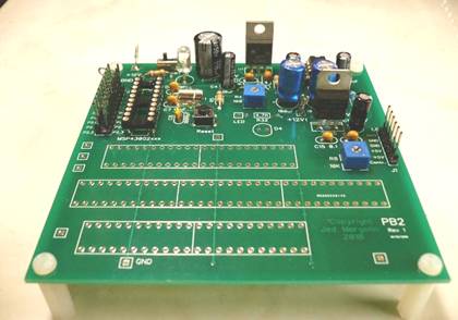
PB2 - Prototyping Board for MSP430G2xxx
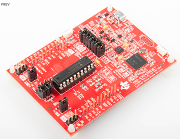
This board is for prototyping circuits with the Texas Instruments MSP430G2xxx microcontroller. It can be used with the Texas Instruments MSP-EXP430G2 Launchpad and the newer MSP-430G2ET Launchpad. It provides 3.3V/3.6V, +12V, -12V, and +5V. After you develop your project with a Launchpad you can disconnect the Launchpad, remove the MSP430G2xxx from the Launchpad, put it on the prototype board, and run it standalone.
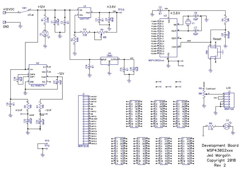
For a PDF of the schematic click here.
The low voltage power supply is adjustable and can be set for voltages between 3.3V and 3.6V. This makes it compatible with both the old Launchpad (MSP-EXP430G2) which operates at 3.6V and the new one (MSP-EXP430G2ET) which operates at 3.3V. The voltage is controlled by trimpot R4.
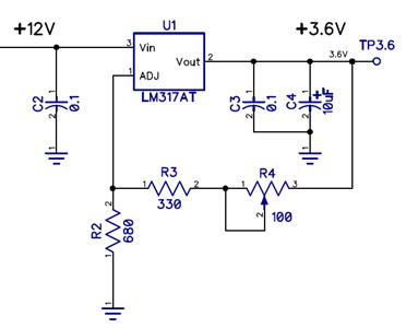
I connected trimpot R4 as a rheostat which is good practice in a circuit like this. The most common failure of potentiometers is the failure of contact between the wiper and the element. It may become erratic (producing noise in an audio circuit like in old radios and TVs) or it may fail completely. If the wiper in R4 fails the circuit resistance will be 100 Ohms and not infinite. In addition I put R4 where it is so that if it has a wiper failure the regulator voltage will go down, not up (it goes down to slightly below 3.3V).
Not everyone does this. I have been using Sunbeam electric blankets for years. They last somewhere between one and maybe five years before the heating element in the blanket gives up. The last time I replaced it the new one was very hot even with the heat setting on ‘1’. I tried the old controller and the heat was where it was supposed to be on ‘1’. I took the new controller apart. The heat control is a pot with mechanical detents for the heat numbers and the pot is read by a microcontroller. I was appalled to discover that it was designed so that if the pot’s wiper failed to make contact with the element the microcontroller considered that a call for maximum heat. This is a safety-critical design since its failure can cause injury or death to Users suffering from medical conditions such as stroke, diabetes, dementia, etc. How could Sunbeam make such a bonehead error? How did this electric blanket make it through Underwriter’s Laboratories? This Sunbeam electric blanket is now old enough that it is dying. My next one (waiting in the closet) is a Biddeford. Hopefully they have gotten it right.
Now back to the board.
1. Use a wire wrap socket for the MSP430G2xxx so you can wire wrap to it, and since the pins of the MSP430G2xxx are connected to the header J1 (except for the clock pins which go to the crystal) they must all be soldered. The MSP430G2xxx is laid out for a 32.768 KHz crystal. For development the J1 header pins are connected to the Launchpad. Once the project is working you can disconnect those wires and plug the programmed MSP430G2xxx into the U3 socket so the project will run standalone.
2. Do not connect the +3.6V on header J1 to the Launchpad. The Launchpad already has power. The reason I put it on the header is to support SPI devices like the BMP-280 temperature/pressure sensor when the proto board is running standalone.
3. The board supports a 16x2 LCD at header J2 with +5V and the contrast control. The data must come from the Launchpad or if you want to run the LCD when the proto board is running standalone you can put a header for the LCD on the proto board and wire the pins to U3. Although the 16x2 LCD panels are available in lower voltage versions I use the standard 5V version. For the datasheet click here. These LCD panels use a Hitachi HD44780 controller. For the datasheet click here. When operated at between 4.5 and 5.5V the HD44780 takes everything above 2.2V as a logic high (PDF page 51). That means you can use it with a 3.3V device without a level translator but you must only write to it. The datasheet does not specify what a logic ‘1’ output is but since it runs on 5V it could be 5V. You have heard of a Read-Only Memory. Well, consider this a Write-Only Memory. It works fine with fixed write timing. The datasheet shows all of the fonts and how to define your own characters.
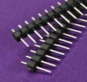
4. I use male headers and connect to the Launchpad with female to female jumper wires. On eBay the headers are called 2.54mm Male PCB Single Row Straight Header Strip Connector Arduino.
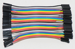
The jumper wires are called 40 Wire Female to Female Jumper Wire for Arduino. They come in various lengths. I suggest you get the 10cm and 20cm lengths. For connecting ground between boards use the 10cm jumpers.
5. Use a wirewrap pin in the test pads such a +12VF and -12VF so you can wirewrap to them. You can use the pins from a wirewrap IC socket that you have sacrificed or you can use the T44, T49, or T68 terminal from Vector Electronics. https://www.vectorelect.com/terminals-wire-wrap.html The header pins that I use (J1 and J2) are square. They are a little smaller than real wirewrap pins but they seem to work and they are a lot cheaper.
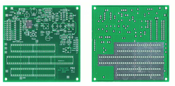
6. I tied the bottom ground strips together with traces on the top layer because I did not want to run bare traces through the pin array.
7. If you look closely you will see the small exposed ground plane under the 32.768 KHz crystal. That is because the 32.768 KHz oscillator sometimes has a problem starting. Sometimes I have to put my finger on the crystal to get the oscillator to start.
I am not the only one with this problem.
Texas Instruments recommends soldering the crystal case to ground. They have a comprehensive discussion of their crystal oscillator. Click here and Click here.
I am hesitant to solder the case because I am afraid of damaging the crystal so I put pads on both sides of the crystal and put small ground plane under it. I solder a piece of #20 bare wire across the crystal into the pads on both sides thereby staking the crystal down. That doesn’t always solve the problem so lately I have been soldering the wire to the crystal case where it touches the top of the crystal. That minimizes the amount of the case that I have to heat up. I have not been doing it long enough to determine if that is a good solution.
Why is this such a problem? There are several possibilities:
1. Blame the crystal.
2. The circuit inside the MSP430G2x that provides the excitation current for the oscillator is very low current in order to keep power consumption as low as possible and it makes oscillator startup marginal.
3. The 32.768 KHz crystal is designed for watches. It appears to be a piezoelectric tuning fork, not a bulk crystal.
a. The reason for the frequency is that if you divide it by 32,768 (2**15) you get 1 second.
b. Something about the capacitance between the tuning fork and the case. I don’t know. That can be a factor with a 16 MHz crystal, but a 32.768 KHz tuning fork?
c. They sell zillions of them for watches so they are very cheap. And because it is designed for selling zillions of watches the case is very thin (giving it low mass) and the wires are very thin. If you just connect the wires they act as springs and the tuning fork ends up with its fanny hanging out in the breeze. That leaves it free to move which affects the tuning fork, lowering its Q. That means it doesn’t resonate as strongly. Soldering it down keeps that from happening.
If I touch the crystal with my finger it helps the oscillator start, probably by damping the motion of the case. If I tap on the crystal with the metal end of a small insulated screwdriver the oscillator starts right up. By doing that I am giving the tuning fork some energy to allow it to start resonating.
Texas Instruments recommends that, at a last resort, you can connect a 750K resistor from XIN to Ground. Click here. I tried that and the oscillator would not start at all.
Let’s talk about the MSP430G2xxx clock oscillators. This information comes from the User’s Guide SLAU144J Basic Clock Module+, PDF page 272. Click here.
There are three oscillator systems.
• VLOCLK: Internal very low power, low frequency oscillator with 12-kHz typical frequency.
• LFXT1CLK: Low-frequency/high-frequency oscillator that can be used with low-frequency watch crystals or external clock sources of 32,768 Hz or external clock sources in the 400-kHz to 16-MHz range. The option to use a high frequency crystal is not present in the MSP430G2xxx.
• DCOCLK: Internal digitally controlled oscillator (DCO).
1. I am not interested in using the 12 KHz (or so) low frequency oscillator.
2. The internal digitally controlled oscillator (DCO) can operate at 16 MHz which is what I want but, unlike other processors, it is not phase locked to the low frequency 32.768 KHz oscillator. It runs open loop. On the other hand it has a very good temperature compensation circuit. After a Reset the device is configured use the DCO running at about 1.1 MHz.
What you do is you get the 32.768 KHz oscillator running and then use that to adjust the DCO. You do that once at startup. However the DCO does not have very high resolution in selecting the frequency. If you are using a part with a UART you will not be able to get the exact standard Baud rates. They do have a kluge for it so the overall timing is almost right.
Some parts of the IC can be run from the 32.768 KHz oscillator or they can all be run off the DCO. If you are using an external oscillator I guess the peripherals would all have to run from that.
And that is the real solution. If I were designing the MSP430G2xxx into a piece of equipment intended for production I would use an external 16 MHz oscillator module. I wouldn’t even make my own oscillator because when you buy an oscillator module it was probably designed by engineers who are experts at designing oscillators and it will work over the temperatures and voltages in the specification. And the company will have strict control over the crystals they buy.
I have some suggestions for Texas Instruments.
1. Coming up from Reset, start the 32.768 KHz oscillator with more excitation current than you do now. Then, once it has started, give the User a bit to reset that reduces the excitation current.
2. For Users who will be using the DCO only, after a Reset start the 32.768 KHz oscillator with more excitation current than you do now. Then, once it has started and the User has set up the DCO, give the User a bit to reset that turns off the excitation current. That will save power. And isn’t that what you want?
3. Let me use a 4 MHz - 16 MHz crystal with the oscillator and you can remove the DCO. Keep the 12 KHz oscillator for those might want it.
The MSP430G2xxx series has been around for a long time. The original designers have probably all retired by now so Texas Instruments might not be able to implement my suggestions even if they wanted to.
I’ll go with my recommendation to use an external oscillator module.
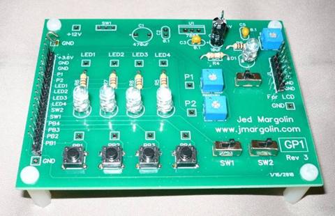
8. You can use this prototyping board with my GP1 board. Use whatever you need from it (pushbutton switches, slide switches, LEDs, pots) and add your circuitry to the prototyping board.
You can use the code I wrote for the GP1 board as a starting point for your own code. Click here.
9. You can order the GP1 board from PCBWAY from this link: https://www.pcbway.com/project/shareproject/GP1____Board_for_demonstrating_how_to_use_an_MSP430G2xxx.html
10. If you are not already a Maker (and you want to be one) see my tutorial on Making Things at
www.jmargolin.com/making/jm_making.htm
11. I am making the DipTrace schematic and PCB files available so you can will have a starting point for designing you own circuits and your own PC boards.
For the DipTrace schematic file click here.
For the DipTrace PCB file click here.
One of the projects I have used it for was when I wondered what pseudo-random noise from a Linear Feedback Shift Register would sound like when it is run through a stereo faker. A stereo faker treats the mono signal as a L+R signal, then delays it and uses the delayed signal as the L-R signal. It then adds the original and delayed signals to form (L+R)+(L-R) = 2L and subtracts the original and delayed signal to form (L+R)-(L-R) = L+R-L+R = 2R. In the frequency domain this forms two comb filters with the combs alternating between the channels. This confuses the brain because it uses phase/time delay to determine the direction of a sound. When it gets fooled like this it decides that the sound must be coming from everywhere.
The distance between the ears (on a human head) is nominally 8.5”. At sea level at standard temperature and pressure sound travels at 767 mph which is 1125 ft/sec. The wave equation is v (velocity) = f (frequency) * λ (wavelength) so that f = v/λ. For v = 1125 ft/sec and λ = 0.71 ft, f = 1584.5 ft/sec / 0.71 = 1584.5/sec which is about 1585 Hz. However, the ear/brain cannot determine the polarity of the phase so that makes the crossover point about 793 Hz. This agrees with Wikipedia’s number of 800 Hz (https://en.wikipedia.org/wiki/Sound_localization)
That means that for a repetitive waveform such as a sine wave, above 800 Hz the phase will repeat making it useless for determining the direction of a sound. However, the brain is also very good at measuring time delay but it must be a sound that is non-repetitive, especially if it contains transients such as clicks. It is not only human brains that are good at this. When a male bird wants to announce his territory but doesn’t want to be exactly located he sings with nice round tones. When he wants to attract a mate he sings with transients (like clicks) so she can find him. The next time you hear a bird singing listen closely to his song and you can tell why he is singing, to announce his territory or to attract a mate.
I programmed the MSP430G2xxx to implement two 31-bit Linear Feedback Shift Registers starting with the same initial seed. Then I clocked only the second one 1250 times. After that I clocked both together. The sequence produced by the first one was therefore always 1250 clocks behind the first one. That is how I produced the delayed pseudo-random noise signal.
For the schematic of my noise stereo test click here. For the source code click here.
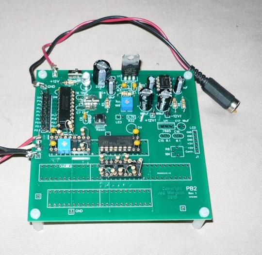
The board.
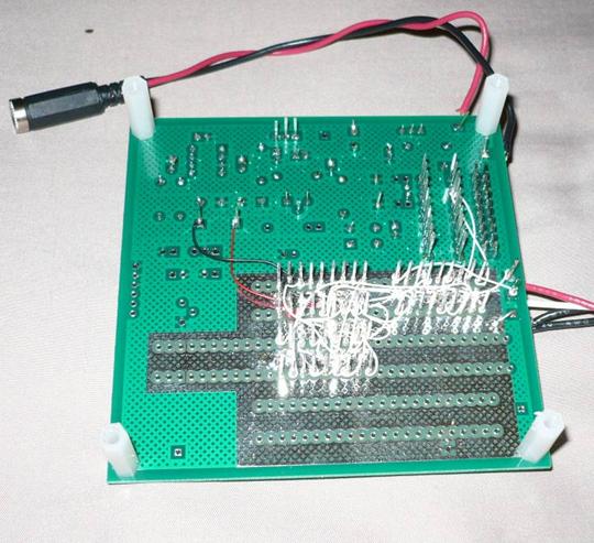
The wirewrap stuff.
I recorded the results so you can hear for yourself what pseudo-random noise sounds like with a stereo faker. I recorded it with Audacity, a very fine program. https://www.audacityteam.org/ using a Behringer U-Control UCA222 USB Audio Interface. The UCA222 has line level inputs and is stereo. The very popular (and cheaper) USB sound pods are only mono.
I recorded it first with the stereo faker turned down, then with it turned up. I repeated it four times. For the mp3 I made click here.
Then I used one of Audacity’s filter to cut the treble 17 dB. For this mp3 click here.
The difference that the stereo faker makes is subtle. You have to listen to it carefully. Listen to it on a system with widely spaced speakers. Listen to it on headphones.
Since the difference is not dramatic I don’t think I will design a PC Board for it. If I did, I would include pink noise filters (Click here.)
The value of my Prototype Board is that I was able to try it out (as a standalone device) without making a dedicated PC Board for it. And now I can reuse the board for another project.
And that is the story about my Prototyping Board for MSP430G2xxx.
The theory of Linear-Feedback-Shift-Registers (LFSRs) is covered extensively in "Shift Register Sequences" by Solomon Golomb (Holden-Day Inc., San Francisco, 1967, and Aegean Park Press, 1982) See Ref 30 and https://en.wikipedia.org/wiki/Solomon_W._Golomb and https://blog.stephenwolfram.com/2016/05/solomon-golomb-19322016/
Now go out and do something splendid.
Jed Margolin
Virginia City Highlands
Nevada
May 30, 2019
.end